
Shale oil hydrotreating process and shale oil hydrotreating system

A technology of hydroprocessing and treatment process, which is applied in the field of oil processing, and can solve problems such as low porosity, increased pressure drop of the catalyst bed, and sudden increase of the pressure drop of the catalyst bed, so as to improve the operation cycle and reduce the pressure drop Effect

Pending Publication Date: 2022-03-18
CHINA PETROLEUM & CHEM CORP +1
View PDF5 Cites 0 Cited by
  • Summary
  • Abstract
  • Description
  • Claims
  • Application Information

AI Technical Summary

Problems solved by technology

[0006] During the research process, the applicant found that the main factor affecting the stable operation of the shale oil hydrogenation unit is that the catalyst bed in the hydrogenation reaction zone that first contacts with the liquid phase material is prone to problems such as deposition of impurities and coking and carbon deposition. As a result, the pressure drop of the catalyst bed increases rapidly, so that the enterprise has to resort to operations such as head skimming and frequent replacement of the catalyst in the reactor, and the existing hydrofining reaction zone is generally only in the catalyst bed that first contacts the liquid phase material A large amount of protective agent is loaded, but the applicant finds after analyzing the deactivated catalyst that there is also a considerable amount of impurities in the deactivated catalyst in the catalyst bed contacting the liquid phase material after the reactor, which is due to the fact that some particles are relatively small After the impurity penetrates the catalyst bed that first contacts the liquid phase material to the catalyst bed that contacts the liquid phase material later, the pressure drop of the catalyst bed increases suddenly because the catalyst bed that contacts the liquid phase material later has no protective agent; All the raw materials are fed from the top of the reactor, resulting in the concentrated deposition of impurities in the raw materials in the catalyst bed where the reactor first contacts the materials. The pressure drop of the bed contacting the liquid phase material becomes the bottleneck restricting the long-term operation of the whole device. When the feed amount of the device fluctuates, impurities are easily carried into the subsequent catalyst bed, and the catalyst bed contacting the material does not contain protective agent and The lower porosity leads to an increase in the pressure drop of the catalyst bed; and because the current existing hydrofinishing reactor is loaded with a large amount of protective agent at the top of the reactor, the loading amount of the hydrofinishing catalyst is relatively reduced, and the addition of the device Hydrogen denitrification capacity is also insufficient, and additional reactors or other means are required to meet the nitrogen content requirements of the product

Method used


Image

  • Shale oil hydrotreating process and shale oil hydrotreating system
  • Shale oil hydrotreating process and shale oil hydrotreating system
  • Shale oil hydrotreating process and shale oil hydrotreating system

Examples


Embodiment 1

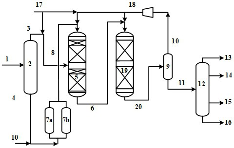
[0069] Taking the whole fraction of inferior shale oil in Table 1 as raw material, adopt figure 1 As shown in the process flow, the raw material is cut into two parts, the light fraction (167°C~350°C) and the heavy fraction (350°C~663°C) by the fractionation tower. The decontamination reactor is set up with three beds. The first bed is filled with TZ-1a, an adsorption catalytic decontamination material. The material shape is a seven-hole ball, the particle diameter is 25mm, and the inner diameter is 2.5mm. Active metal; the second bed is filled with TZ-2a, an adsorption catalytic impurity removal material, whose material shape is bird's nest type, the particle diameter is 18mm, the pore volume is 0.50mL / g, and the alumina is used as the matrix MoO 3 The component content is 6.5wt%, and the NiO component content is 1.2wt%; the third bed is filled with TZ-3a, an adsorption catalytic impurity removal material, whose material shape is Raschig ring type, the particle diameter is 8m...

Embodiment 2

[0071] Taking the whole fraction of inferior shale oil in Table 1 as raw material, adopt figure 1 As shown in the process flow, the raw material is cut into two parts, the light fraction (167°C~300°C) and the heavy fraction (300°C~663°C) by the fractionation tower. The decontamination reactor is set up with three beds, the first bed is filled with TZ-1b, an adsorption catalytic decontamination material, whose material shape is seven-hole sphere, the particle diameter is 20mm, the inner pore diameter is 1.8mm, and alumina is used as the matrix MoO 3 The component content is 7.5wt%; the second bed is filled with adsorption catalytic impurity removal material TZ-2b, whose material shape is bird's nest type, the particle diameter is 12mm, the pore volume is 0.45mL / g, and alumina is used as the matrix MoO 3 The component content is 8.5wt%, and the NiO component content is 1.5wt%; the third bed is filled with TZ-3b, an adsorption catalytic impurity removal material, whose material s...

Embodiment 3

[0073] Taking the whole fraction of inferior shale oil in Table 1 as raw material, adopt figure 2 As shown in the process flow, the raw material is cut into two parts, the light fraction (167°C~339°C) and the heavy fraction (339°C~663°C) by the fractionation tower. The decontamination reactor is set up with three beds, the first bed is filled with TZ-1c, an adsorption catalytic decontamination material. 3 The component content is 1.0wt%; the second bed is filled with adsorption catalytic impurity removal material TZ-2c, whose material shape is bird's nest type, the particle diameter is 24mm, the pore volume is 0.52mL / g, and alumina is used as the matrix MoO 3 The component content is 3.5wt%, and the NiO component content is 0.25wt%; the third bed is filled with TZ-3c, an adsorption catalytic impurity removal material, whose material shape is Raschig ring type, the particle diameter is 17.5mm, and the pore volume is 0.59 mL / g, with alumina as matrix MoO 3 The component conte...


PUM

PropertyMeasurementUnit
Diameteraaaaaaaaaa
Inner diameteraaaaaaaaaa
Diameteraaaaaaaaaa

Abstract

The invention discloses a shale oil hydrotreating process and a shale oil hydrotreating system, and the shale oil hydrotreating process comprises the following steps: cutting a shale oil raw material to obtain a light fraction and a heavy fraction, respectively feeding the light fraction and the purified heavy fraction into a hydrogenation reaction zone, and reacting in the presence of hydrogen, and separating the reaction effluent to obtain hydrogen-containing gas and refined shale oil. The treatment system comprises a fractionating tower, an impurity removal reaction zone, a hydrogenation reaction zone and a separation unit. According to the treatment process, shale oil raw materials can be treated for a long period, and the denitrification capacity of the device is effectively improved.

Description

technical field [0001] The invention belongs to the technical field of oil processing, and in particular relates to a shale oil hydrotreating process and a processing system. Background technique [0002] Among the natural resources, oil shale, like oil, is mainly generated by lower plankton such as algae through decay and coalification. The shale oil "squeezed" from oil shale is called "artificial oil" through low carbonization and other methods. After further processing and refining, liquid fuels such as gasoline, kerosene, and diesel can be obtained. In the early stage of oil shale mining, the development of this industry was limited due to insufficient technology and environmental pollution in the production process. In recent years, with the advancement of technology, this problem has been well resolved. It is foreseeable that under the current situation of shortage of oil resources and soaring oil prices, shale oil will play an increasingly important role in the petr...

Claims


Application Information

Patent Timeline
IPC IPC(8): C10G67/02
CPCC10G67/02C10G2300/4006C10G2300/4012C10G2300/4018C10G2300/70
Inventor 范思强黄新露吴子明曹正凯彭冲王仲义庞宏崔哲孙士可白振民
Owner CHINA PETROLEUM & CHEM CORP
Learn More