


Quick Research
Generate reliable direction feasibility study reports for your R&D in just a few steps.

Technical Q&A
Discover and master advanced knowledge NOW. Basics, ideas, possibilities, all at once.

Find Solutions
As an expert in R&D theories, this can generate solutions to your technical problems instantly.

Evaluate Feasibility
Analyze your overall solution with one click, know your potential R&D risks in advance.

Monitor Landscape
Get weekly tech updates, stay abreast of the latest tech innovations and key insights.
Air cylinder pneumatic oiling device with high safety
A safety, cylinder technology, used in mixers with rotary stirring devices, pumps with negative pressure, transportation and packaging, etc., can solve problems such as excess or overflow of oil, excessive output of oil, affecting equipment operation, etc. The effect of preventing sticking, avoiding excessive output, avoiding spillage
- Summary
- Abstract
- Description
- Claims
- Application Information
AI Technical Summary
Problems solved by technology
Method used
Image

Examples
Embodiment 1
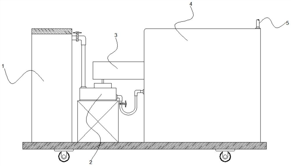
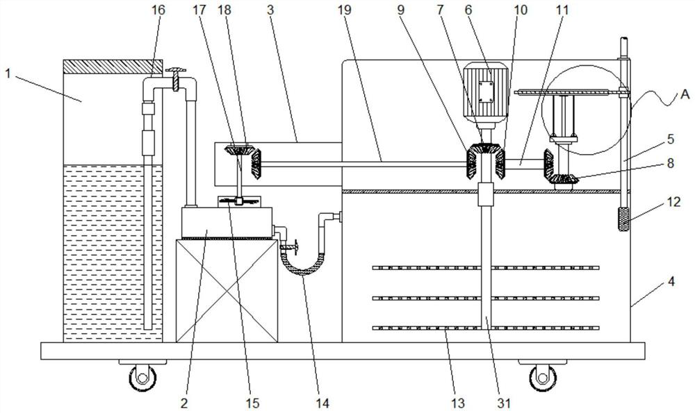
[0042] see Figure 1 to Figure 7 , in an embodiment of the present invention, a cylinder pneumatic oiling device with high safety includes an oil storage tank 1 for storing oil, and the oil storage tank 1 communicates with an oil treatment tank 4 that processes the oil and outputs it to the outside , the oil treatment box 4 is connected with an oiling pipe 5, and the upper end of the oiling pipe 5 passes through the pressure nozzle outside the hose connection part, and a pressure nozzle of a suitable caliber can be installed according to the needs of specific equipment; the oil treatment box 4 A horizontal partition is arranged in the middle, and the partition divides the oil treatment tank 4 into an upper device room and a lower oil treatment room. The device room of the oil treatment tank 4 is equipped with a motor whose output end is set downward. 6. The output end of the motor 6 is connected to the vertical output shaft 31 extending into the oil treatment chamber at the lo...
Embodiment 2
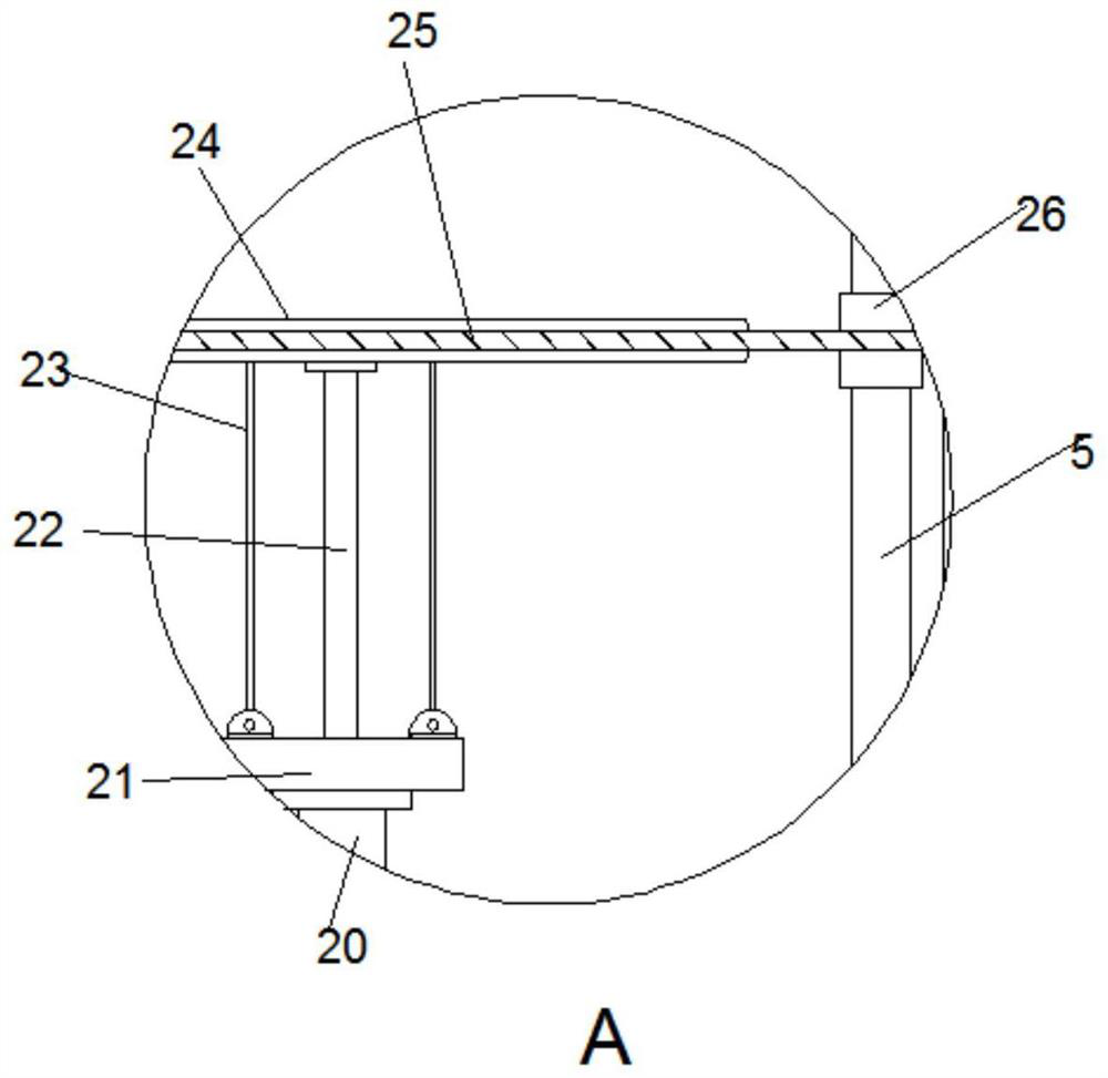
[0048] see Figure 8 , on the basis of Embodiment 1, the embodiment of the present invention further improves the working effect of a highly safe cylinder pneumatic oiling device, specifically:
[0049] The second transmission helical gear set 8 includes a vertical helical gear 801 connected to the secondary transmission shaft 11 and a horizontal helical gear 802 connected to the second rotating shaft 20, the vertical helical gear 801 is an intermittent gear; When the straight helical gear 801 rotates with the horizontal helical gear 802, when its tooth pattern segment rotates to mesh with the horizontal helical gear 802, the second rotating shaft 20 will rotate accordingly. At this time, the rotational drive received by the second rotating shaft 20 stops immediately, and the direct result is that the top plate 24 moves up and down in a certain range during the process of descending, and is driven by the connecting piece 25. The oil pipe 5 follows and shakes up and down synch...
Embodiment 3
[0051] see Figure 9 ~ Figure 13 , on the basis of the embodiment and embodiment 2 in this embodiment, it is proposed to carry out the flow-dependent injection assembly of the relevant additives in the oil treatment tank 4, specifically:
[0052] The oil treatment tank 4 is also provided with an additive feeding assembly for adding additives to the oil entering the oil treatment tank 4. The additive feeding assembly includes an impeller 32, a driving gear 33, a barrel 36 and a touch lever 37. The impeller 32 is rotated and installed at the connection between the oil treatment tank 4 and the oil delivery U-shaped pipe 14, and the oil entering the oil treatment tank 4 is transported through the oil delivery U-shaped pipe 14 and then passes through the impeller 32 and drives the impeller 32 rotates, the drive gear 33 is coaxially arranged with the impeller 32, and the drive gear 33 rotates with the impeller 32. The oil treatment tank 4 is provided with a barrel 36 for loading oil...
PUM
 Abstract
Description
Claims
Application Information
 - R&D Engineer
- R&D Manager
- IP Professional
- Industry Leading Data Capabilities
- Powerful AI technology
- Patent DNA Extraction
Browse by: Latest US Patents, China's latest patents, Technical Efficacy Thesaurus, Application Domain, Technology Topic, Popular Technical Reports.
© 2024 PatSnap. All rights reserved.Legal|Privacy policy|Modern Slavery Act Transparency Statement|Sitemap|About US| Contact US: help@patsnap.com