Multi-energy gradient utilization heat pump low-temperature evaporation and concentration system capable of accurately controlling temperature

A low-temperature evaporation and concentration system technology, which is applied in the fields of industrial technology, energy and environmental protection, can solve the problems of reducing the available heat for heating materials, affecting steam, and reducing system energy efficiency, so as to reduce the possibility of adhesion or coking and ensure vacuum pressure , The effect of improving the energy efficiency of the system

Pending Publication Date: 2022-03-01
李爱松
View PDF0 Cites 3 Cited by
  • Summary
  • Abstract
  • Description
  • Claims
  • Application Information

AI Technical Summary

Problems solved by technology

In the existing reverse Carnot cycle heat pump vacuum low-temperature evaporation and concentration system, the heating side of the material (condenser side) generally uses refrigerant to directly pass into the heat-exchanging parts with the material partition wall. This method has many technical problems: (1) The temperature of the gaseous refrigerant at the outlet of the compressor in the heat pump cycle is very high and fluctuates greatly. If it is directly fed into the heat exchange component, it will cause the material on the evaporation surface at the inlet position of the heat exchange component to undergo instantaneous over-temperature denaturation or excessive evaporation. hot
If the temperature is lowered by adding heat dissipation parts on the outlet pipeline of the compressor, it will not only reduce the available heat for heating the material, but also increase the power consumption for cooling and heat exchange, and at the same time, the pre-cooling of the gaseous refrigerant itself also has the problem of poor temperature controllability. The inlet temperature fluctuation of the refrigerant that exchanges heat with the material increases, and the temperature cannot be accurately controlled; (2) During the sensible heat cooling process of the high-temperature gaseous refrigerant before condensation and the sensible heat supercooling process of the liquid refrigerant, the heating tank plate is used Compared with the plate heat exchanger, the heat transfer effect of the tube or the inner wall of the sleeve is poor. It is necessary to increase the heat transfer area of ​​the coil or the sleeve wall, which will occupy the capacity of the material in the evaporation tank, and will also cause the condenser to Increased side resistance or flow rate further increases the discharge temperature of the compressor
(3) Measures or measures to enhance heat transfer on the material-liquid side that are suitable for heat-sensitive materials or special waste water and waste liquids are not considered or the measures are not effective, resulting in insufficient thermal driving force for steam overflow inside the material, hindering evaporation and heat transfer, and making the heating temperature much higher Above the boiling point, the superheat of the steam is higher, which not only increases the steam condensation load in the later stage, but also forms more foam due to excessive boiling, which affects the dryness of the steam, resulting in increased energy consumption for equipment operation
(4) Since the heat release side of the condensation includes the heat produced by the compressor, in order to maintain the heat and cold balance of the heat pump cycle, the general practice is to install an air cooling device in front of the throttle valve to discharge this part of the heat (making the heat pump cycle change becomes a refrigeration cycle), and is used to increase the subcooling degree before throttling, and this part of heat is not used as heat loss, which reduces the energy efficiency of the system
(5) The refrigerant side of the condenser is at high pressure, and the material side is at high vacuum. When the two directly exchange heat between the walls, the pressure difference on both sides of the heat exchange wall is very large. The requirements for materials and processing are very high, which increases the cost and refrigerant. leakage risk
[0005] The main technical problems of the existing heat pump vacuum low-temperature evaporation and concentration system on the steam condensation side (evaporator side) include: (1) The heat exchange efficiency of traditional heat exchange coils or finned tubes is low, causing the evaporation temperature to be much lower than the steam condensation temperature , reducing the system energy efficiency
At the same time, when the amount of secondary steam is large, the vacuum degree in the device will not be reduced in time due to the condensation heat exchange, which will increase the operating energy consumption of the vacuum equipment; As a result, there is no steam contact with the heat exchange components, which deteriorates the working conditions of the refrigeration cycle. At present, the method of adding auxiliary electric heaters is generally adopted to solve this problem, which further increases the energy consumption of the system.
(3) The existing technology does not consider the problem of the grade of heat energy of the ladder, because the temperature of the steam is high, and the temperature gradient between the condensation temperature of the steam and the evaporation temperature of the refrigerant is very large, and the cascade condensation cannot be realized by relying on a single refrigerant cooling method, which reduces the system temperature. (4) The existing heat pump vacuum low-temperature evaporation and concentration technology does not fully consider the use of high-efficiency secondary steam condensation heat exchange, which makes the evaporation temperature low, resulting in low energy efficiency of the heat pump cycle system

Method used


Image

  • Multi-energy gradient utilization heat pump low-temperature evaporation and concentration system capable of accurately controlling temperature

Examples


Embodiment Construction

[0049] The technical solutions of the present application are described in detail below in conjunction with specific embodiments.

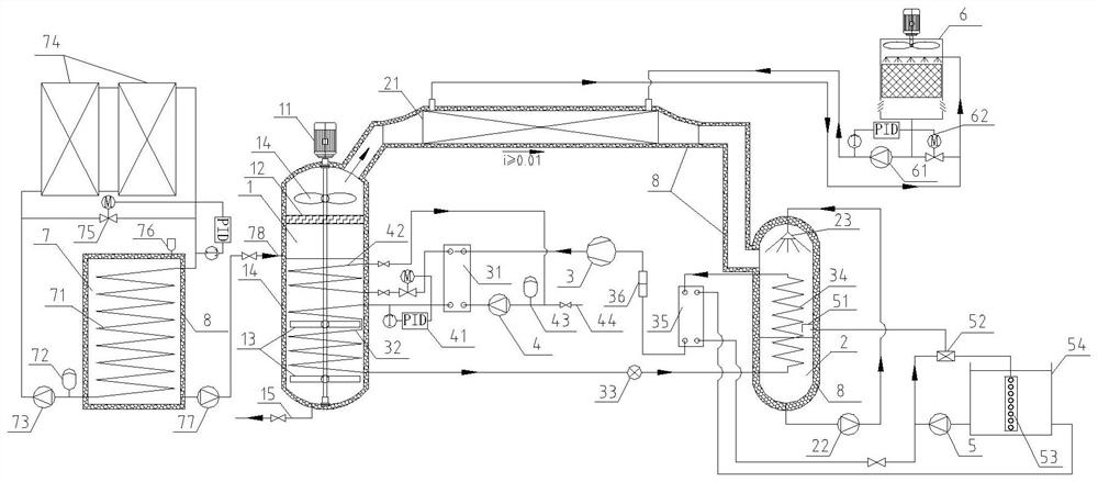
[0050] According to the present invention, the multi-energy cascade heat pump low-temperature evaporation and concentration system capable of precise temperature control includes a heating tank, a steam cooling and condensation system, a heat pump circulation system, a vacuum pumping and recondensation system, a water circulation temperature adjustment system, a heat dissipation system, and a material pretreatment system. thermal system, where,

[0051] A stirring motor is arranged above the outside of the heating tank, a fan blade, a defoaming device, and a stirring blade are arranged inside the heating tank, and a concentrated material liquid outlet pipe is arranged at the bottom, and the stirring motor provides the power for the stirring blade and the fan blade to rotate, and the heating The tank is provided with an insulation layer;

[0052] ...


PUM


Abstract

The invention belongs to the field of industrial processes, energy and environmental protection, and particularly relates to a multi-energy gradient utilization heat pump low-temperature evaporation and concentration system capable of accurately controlling temperature. The multi-energy gradient utilization heat pump low-temperature evaporation and concentration system capable of accurately controlling the temperature comprises a heating tank, a steam cooling and condensing system, a heat pump circulating system, a vacuumizing and re-condensing system, a water circulating temperature adjusting system, a heat dissipation system and a material preheating system. According to the system, efficient heat exchange on the refrigerant side can be achieved, the pressure environment of the material heating coil is improved, the adverse problems caused by heating materials through a high-temperature refrigerant are effectively solved, the material treatment quality is improved, meanwhile, the superheat degree of secondary steam can be reduced, and the heat exchange environment on the evaporator side during initial starting is improved. The system can accurately control the boiling evaporation temperature of the materials and efficiently utilize the materials in a gradient manner according to energy grades, so that the purposes of saving energy and reducing carbon are achieved, and the system is very significant.

Description

technical field [0001] The invention belongs to the fields of industrial technology, energy and environmental protection, and in particular relates to a multi-energy cascade utilization heat pump low-temperature evaporation concentration system capable of precise temperature control. Background technique [0002] Energy issues and environmental issues have become increasingly prominent in industrial production, which puts forward higher requirements for energy-saving technologies. In particular, the proposal of dual-carbon targets puts forward new target requirements for energy conservation and carbon reduction in the industrial field. In the industrial field, evaporation and concentration is a very common heat treatment process for materials, and it is also an important link in energy consumption and carbon emissions. The use of energy-saving and carbon-reducing technologies in this process is of great significance to energy and environmental protection. [0003] In the ev...

Claims


Application Information

Patent Timeline
IPC IPC(8): B01D1/22B01D1/16B01D1/26B01D1/30
CPCB01D1/22B01D1/16B01D1/26B01D1/30
Inventor 李爱松
Owner 李爱松
Why Eureka
Try Eureka