
Skin CT large-field-of-view image splicing method and system with high reliability and fault tolerance

An image mosaic and CT image technology, applied in the fields of image mosaic details, image enhancement, image analysis, etc., can solve the problem of inaccurate image mosaic, reduce patient shaking, improve computing efficiency, ensure integrity and robustness sticky effect

Pending Publication Date: 2022-01-11
SUZHOU INST OF BIOMEDICAL ENG & TECH CHINESE ACADEMY OF SCI
View PDF0 Cites 2 Cited by
  • Summary
  • Abstract
  • Description
  • Claims
  • Application Information

AI Technical Summary

Problems solved by technology

In addition, because the microscope objective lens needs to be moved during the splicing process, usually the motor drives the objective lens to move and shoot, and the motor will also produce a certain deviation in the process of moving a fixed number of steps, resulting in the inability to accurately splice the images

Method used


Image

  • Skin CT large-field-of-view image splicing method and system with high reliability and fault tolerance
  • Skin CT large-field-of-view image splicing method and system with high reliability and fault tolerance
  • Skin CT large-field-of-view image splicing method and system with high reliability and fault tolerance

Examples


Embodiment 1

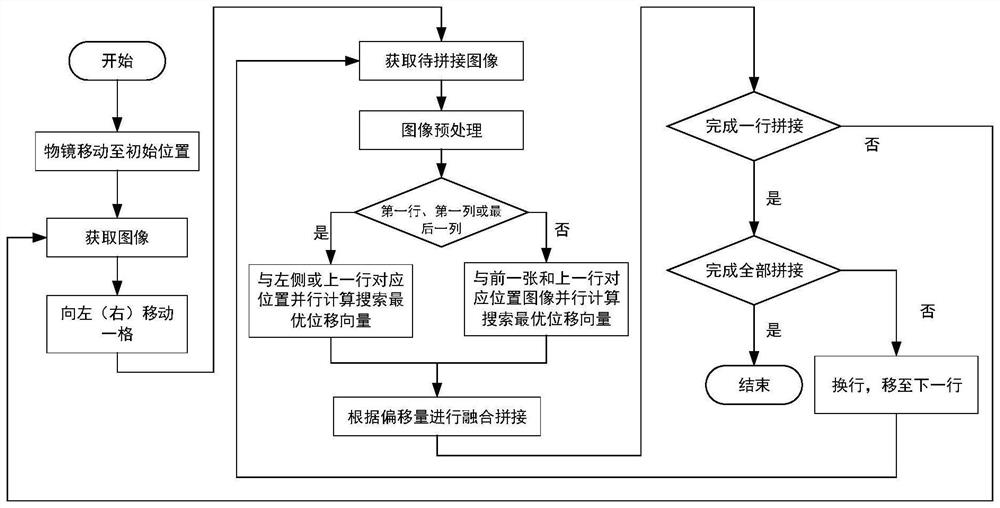
[0054] refer to figure 1 , a highly reliable and fault-tolerant skin CT large-field image stitching method of the present embodiment, comprising:

[0055] 1. Manually determine the starting point and size of the splicing area, and set the M rows×N columns of skin CT images to be spliced ​​according to the grid shape, so as to ensure that the left, right, upper and lower adjacent images have overlapping areas;

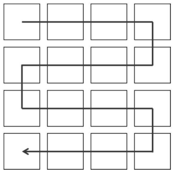
[0056] 2. Make the objective lens of the dermatoscope scan each grid in the first row from left to right from the starting point of the splicing area, then switch to the next row and move in the opposite direction, and cycle like this to complete all the grids along the S-shaped trajectory scan, see figure 2 ;

[0057] During the scanning process of the objective lens of the dermatoscope, the skin CT image of the current grid is obtained first, and then the acquired skin CT image is stitched onto the large-field skin CT image that has been stitched before scanning th...

Embodiment 2

[0089] This embodiment provides a highly reliable and fault-tolerant skin CT large-field image stitching system, which adopts the method in Embodiment 1 to stitch skin CT large-field images.

[0090] This embodiment also provides a storage medium on which a computer program is stored, and the program is used to implement the method in Embodiment 1 when executed.

[0091] This embodiment also provides a computer device, including a memory, a processor, and a computer program stored in the memory and operable on the processor, and the processor implements the method in Embodiment 1 when executing the computer program.


PUM


Abstract

The invention discloses a skin CT large-field-of-view image splicing method and system with high reliability and fault tolerance, and the method comprises the steps: 1), manually determining the starting point and size of a splicing region, setting M rows * N columns of skin CT images needing to be spliced according to the shape of a grid, and guaranteeing that the left and right adjacent images and the upper and lower adjacent images have an overlapping region; and 2), enabling an objective lens of a dermatoscope to sequentially scan each grid in the first row from left to right from the starting point of the splicing area, then changing to the next row and performing reverse movement, repeating the steps, completing scanning of all grids along the S-shaped track, and performing splicing while obtaining images. According to the method, a fault-tolerant mechanism is introduced, so that the situation that overall splicing fails due to local image splicing errors in the large-view-field splicing process is avoided, an error area is limited in a local small range, and the robustness and efficiency of large-view-field image splicing are improved.

Description

technical field [0001] The invention relates to the field of skin CT detection, in particular to a high-reliability and fault-tolerant skin CT large-field image splicing method and system. Background technique [0002] Skin CT imaging is based on the confocal principle, adding an in-body scanning device to the confocal laser scanning microscope, thereby realizing the non-invasive observation of cell characteristics at different structural levels of the skin. [0003] Skin CT scans the subcutaneous tissue to obtain grayscale images, which are usually grayscale images of varying degrees of brightness based on the differences in the refractive index of light in the microstructure of the skin tissue, such as melanin, oxygenated hemoglobin, and organelles. During the scanning process of skin CT, if the laser is too strong (too weak), the overall image will be too bright (dark), resulting in different tissue structures that cannot be correctly distinguished. Therefore, it is neces...

Claims


Application Information

Patent Timeline
IPC IPC(8): G06T3/40G06T7/00
CPCG06T3/4038G06T7/0012G06T2200/32G06T2207/10081G06T2207/30088
Inventor 陈振鑫党世杰王佳俊张洪远杨雨澄赵凌霄
Owner SUZHOU INST OF BIOMEDICAL ENG & TECH CHINESE ACADEMY OF SCI
Learn More