Numerical control end face cylindrical grinding machine for efficiently and ultraprecisely grinding high-speed cutter handle

A cylindrical grinding machine and ultra-precision technology, which is applied to machine tools designed for grinding the rotating surface of workpieces, grinding machine parts, and grinding machines. problems, to achieve the effect of reducing labor dependence, reducing adjustment time, and saving labor costs

Pending Publication Date: 2022-01-11
济南凯特尔机器有限公司
View PDF10 Cites 3 Cited by
  • Summary
  • Abstract
  • Description
  • Claims
  • Application Information

AI Technical Summary

Problems solved by technology

The first is: the over-positioning structure of the handle makes it difficult to control the size of the grinding. If the manufacturer lacks special finishing equipment, it will rely heavily on operators with industry and production experience.
As a result, these experienced industrial workers are competed by many companies, which aggravates labor costs and instability
Second, it is precisely because of the difficulty in processing this type of knife handle that the price of this type of knife handle is relatively high, which attracts many manufacturers to produce it. At the same time, due to the variety of categories, it is difficult for most manufacturers to produce in large quantities.
The grinding part happens to be the closest to the tailstock, so every adjustment will force to update the grinding parameters and coordinates, and adjust the position of the gauge. What’s more troublesome is that the movement of the tailstock often causes the taper of the workpiece to change, and the adjustment Shank taper is very time consuming

Method used


Image

  • Numerical control end face cylindrical grinding machine for efficiently and ultraprecisely grinding high-speed cutter handle
  • Numerical control end face cylindrical grinding machine for efficiently and ultraprecisely grinding high-speed cutter handle
  • Numerical control end face cylindrical grinding machine for efficiently and ultraprecisely grinding high-speed cutter handle

Examples


Embodiment Construction

[0036] The content of the present invention will be further described in detail below in conjunction with the accompanying drawings.

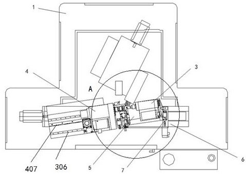
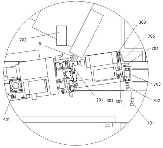
[0037] A CNC end face cylindrical grinder for high-efficiency ultra-precision grinding of high-speed tool handles, including a bed 1, a tool handle outer diameter measuring instrument 201, an end surface measuring instrument 202, a tailstock device 3, a headstock device 4, an upper workbench 5, The lower workbench 6 and the upper workbench angle adjustment device 7 also include a coolant tank on which a constant temperature air conditioner is installed; the inside of the coolant tank is provided with a precision filter bag filter. A V-shaped workpiece bracket 9 is arranged between the tailstock device 3 and the headstock device 4 .

[0038] The coolant tank is equipped with a constant temperature air conditioner, which can adjust the temperature within 0.5 degrees Celsius. The coolant tank is equipped with a precision filter bag filter, which can...


PUM


Abstract

The invention mainly relates to the field of numerical control grinding machines, in particular to a numerical control end face cylindrical grinding machine for efficiently and ultraprecisely grinding a high-speed cutter handle. The cylindrical grinding machine comprises a machine body, a knife handle outer diameter measuring instrument, an end face measuring instrument, a tailstock device, a headstock device, an upper workbench, a grinding wheel, a lower workbench and an upper workbench angle adjusting device. The tailstock device and the headstock device are arranged on the upper workbench, and the headstock device can move in the connecting line direction of the tailstock device and the headstock device; the knife handle outer diameter measuring instrument is arranged between the tailstock device and the headstock device; and the end face measuring instrument is arranged on one side of the grinding wheel and can measure the end face position of a workpiece. The grinding machine is controlled through a numerical control system, positioning conical surfaces and end faces of various cutter handles can be accurately ground at a time, and one-time machining can be qualified, efficient and stable. The cost and the dependence on operators can be greatly reduced, and the high machining precision is achieved.

Description

technical field [0001] The invention mainly relates to the field of numerical control grinding machines, in particular to a numerical control end face cylindrical grinding machine for high-efficiency ultra-precision grinding of high-speed tool handles. Background technique [0002] In today's machining, various types of high-end machining centers using high-speed milling and drilling are becoming more and more common. As a tool holder for holding high-speed rotating tools, it is the core component that affects machining accuracy and efficiency, and is also one of the wearing parts of this type of machine tool. one. At present, there are two types of high-speed tool holders that are most used in my country: HSK tool holders and BBT tool holders. The structures of these two tool holders can reach tens of thousands of revolutions per minute. The maximum speed of the traditional BT handle is only 5000 rpm. As we all know, high-speed rotating tools will generate high centrifuga...

Claims


Application Information

Patent Timeline
Patent Type & Authority Applications(China)
IPC IPC(8): B24B5/36B24B5/35B24B41/04B24B41/06B24B47/22
CPCB24B5/36B24B5/35B24B41/067B24B41/04B24B47/22Y02P70/10
Inventor 杨凯
Owner 济南凯特尔机器有限公司
Why Eureka
Try Eureka