Large-delay-inequality dispersion waveguide structure

A technology of waveguide structure and delay difference, which is applied in the field of optical communication, can solve the problems of difficult realization, low spectral width, large dispersion, etc., and achieve the effect of reducing complexity and process accuracy requirements, large delay difference, compact structure, and simple process

Active Publication Date: 2022-01-07
SOUTHEAST UNIV
View PDF24 Cites 0 Cited by
  • Summary
  • Abstract
  • Description
  • Claims
  • Application Information

AI Technical Summary

Problems solved by technology

In these schemes, the Bragg grating structure needs to finely control parameters such as waveguide size, interface smoothness, grating position, and refractive index changes. Ring resonators can only achieve small time delays and low spectral widths, and optical switches switch optical paths. The need for several optical switches introduces crosstalk
In addition, since the loss of these structures is proportional to the length of the path passed, the high in-band flatness requirement in the case of wide spectrum and high dispersion requirements means that there must be very low insertion loss, which is more difficult to achieve
To realize a dispersion waveguide with wide spectrum, large dispersion, low jitter, and high flatness, the existing structural schemes cannot meet the requirements

Method used


Image

  • Large-delay-inequality dispersion waveguide structure
  • Large-delay-inequality dispersion waveguide structure
  • Large-delay-inequality dispersion waveguide structure

Examples


Embodiment Construction

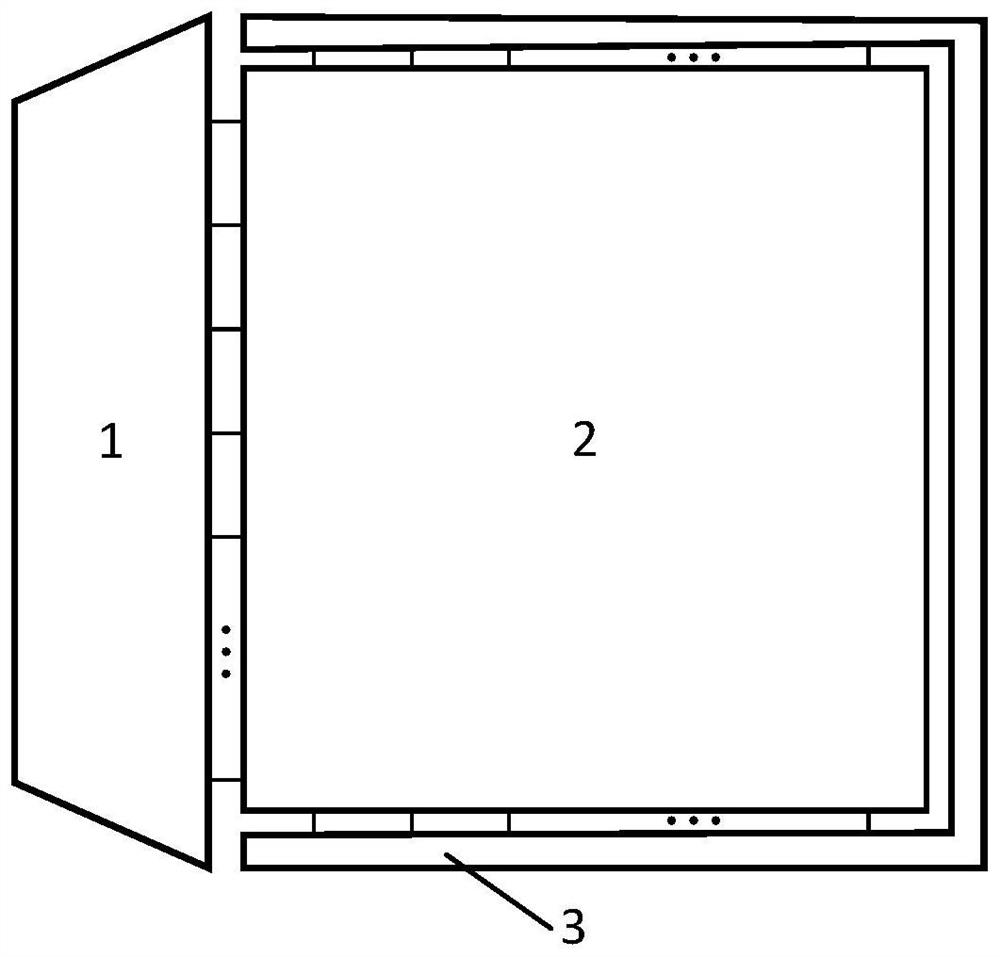
[0040] A large delay difference dispersion waveguide structure, such as figure 1 As shown, a three-stage structure of wavelength division-delay array-reflection is adopted, including wavelength division multiplexing unit 1, delay array 2 and reflection stage 3; wavelength division multiplexing unit 1 demultiplexes the incident multi-wavelength multiplexing signal It is used at the demultiplexing end and connected to the delay array 2; the delay array 2 delays the signals of different ports of the demultiplexing end differently; the reflection stage 3 reflects the light of each waveguide branch at the end of the waveguide of the delay array 2 Back to the incident end.

[0041] An implementation of the wavelength division multiplexing unit 1 in the present invention is based on an arrayed waveguide grating (AWG) structure.

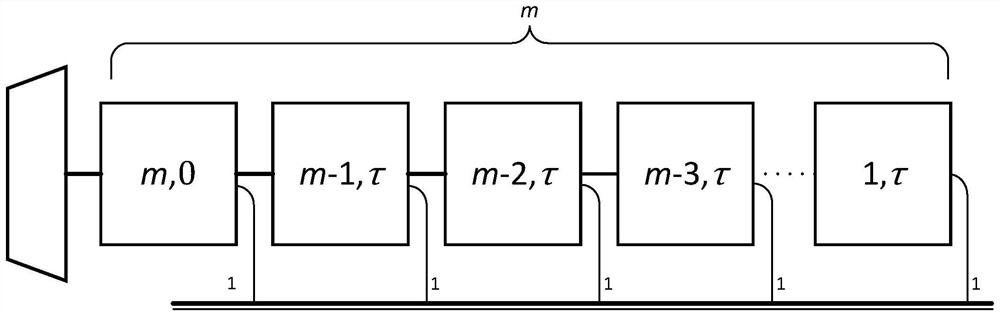
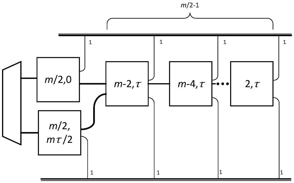
[0042] The dispersive delay array 2 is based on the waveguide bus delay array to form a delay network, which realizes low jitter and large dispersion in a ...


PUM


Abstract

The invention discloses a wavelength division-time delay array-reflection type large-time-delay-difference dispersion waveguide structure which comprises a wavelength division multiplexing unit, a time delay array and a reflection level. A wavelength division multiplexing unit can be realized based on an array waveguide grating structure and is used for demultiplexing a multi-wavelength multiplexing signal to a wave division end; a dispersion delay array forms a delay network based on waveguide bus delay units to realize low jitter and large dispersion in a large wavelength range; a final reflection stage is used for reflecting all wavelengths. For a large delay demand, the delay unit realizes a compact large delay unit by using an S-spiral structure of a waveguide bus, and realizes high-dispersion slope dispersion by using cascade connection between dispersion units. Compared with an FBG-based dispersion structure, the structure is simpler in preparation process and easier to realize low-delay jitter in a wide spectrum range. In conclusion, the dispersion waveguide chip structure provided by the invention has the characteristics of wide spectrum, high dispersion / large delay inequality, simple process and small jitter.

Description

technical field [0001] The invention relates to the technical field of optical signal delay control, in particular to the technical fields of optical communication technology and microwave photonics. Background technique [0002] Dispersion delay structures have a wide range of applications in microwave photonic technology fields such as dispersion control / compensation, sensing, communication, optical signal processing, phased array antennas, and beamforming. In order to meet the needs of large-scale high-precision phase / delay adjustment, etc., the dispersive delay structure needs to have characteristics such as large group delay difference, large bandwidth, low insertion loss, good in-band flatness, and low delay jitter. [0003] So far, most of the realization schemes of the dispersion delay structure are based on the discrete components to build the system. A typical structure is realized by fiber Bragg grating, such as uniform fiber grating, chirped fiber grating, apodi...

Claims


Application Information

Patent Timeline
Patent Type & Authority Applications(China)
IPC IPC(8): H04B10/2513G02B6/12G02B6/293
CPCH04B10/2513G02B6/12009G02B6/29392
Inventor 樊鹤红孙文睿孙小菡
Owner SOUTHEAST UNIV
Why Eureka
Try Eureka