Fuel cell thermal management system based on magnetic heat and control method

A thermal management system and fuel cell technology, applied in the fields of fuel cell heat exchange, fuel cell, fuel cell additives, etc., can solve the problems of reduced electrochemical active surface area, cold start failure, low cold start temperature, etc.

Active Publication Date: 2022-01-07
CHINA THREE GORGES NEW ENERGY CO LTD
View PDF7 Cites 0 Cited by
  • Summary
  • Abstract
  • Description
  • Claims
  • Application Information

AI Technical Summary

Problems solved by technology

[0003] When the fuel cell is started in a low temperature environment below 0°C without taking any protective measures, the water produced by the reaction will first freeze inside the catalytic layer, resulting in the covering of the active sites of the catalytic layer and the transmission of oxygen. Blocked, the voltage drops suddenly; when the catalytic layer is completely covered by ice and the stack temperature has not risen above 0°C, ice will form in the diffusion layer and flow channel, resulting in cold start failure
On the other hand, the freezing process of the catalytic layer can lead to gaps between the catalytic layer and the proton exchange membrane, while the freezing / thawing cycle can cause the collapse and densification of the microporous structure of the catalytic layer and the coarsening of platinum particles in the catalytic layer. , resulting in the reduction of the electrochemically active surface area and it is difficult to recover, thereby causing permanent damage to the power generation performance of the fuel cell, and the more cycles, the lower the cold start temperature, the greater the damage to the battery
[0004] At present, the technical solution for low-temperature start-up of the fuel cell is mainly to use gas purging to reduce the water content of the fuel cell membrane electrode when the stack is shut down, thereby reducing the formation of solid ice, but only when the stack temperature does not rise above 0°C When the stack produces water, it will freeze, and first of all, ice will be generated on the surface of the platinum particles in contact with the ion resin. Once the temperature rises to room temperature, the ice at the interface between the platinum and the ion resin will melt and cause the interface to detach, resulting in an irreversible electrochemical reaction. loss of active area

Method used


Image

  • Fuel cell thermal management system based on magnetic heat and control method
  • Fuel cell thermal management system based on magnetic heat and control method
  • Fuel cell thermal management system based on magnetic heat and control method

Examples


Embodiment 1

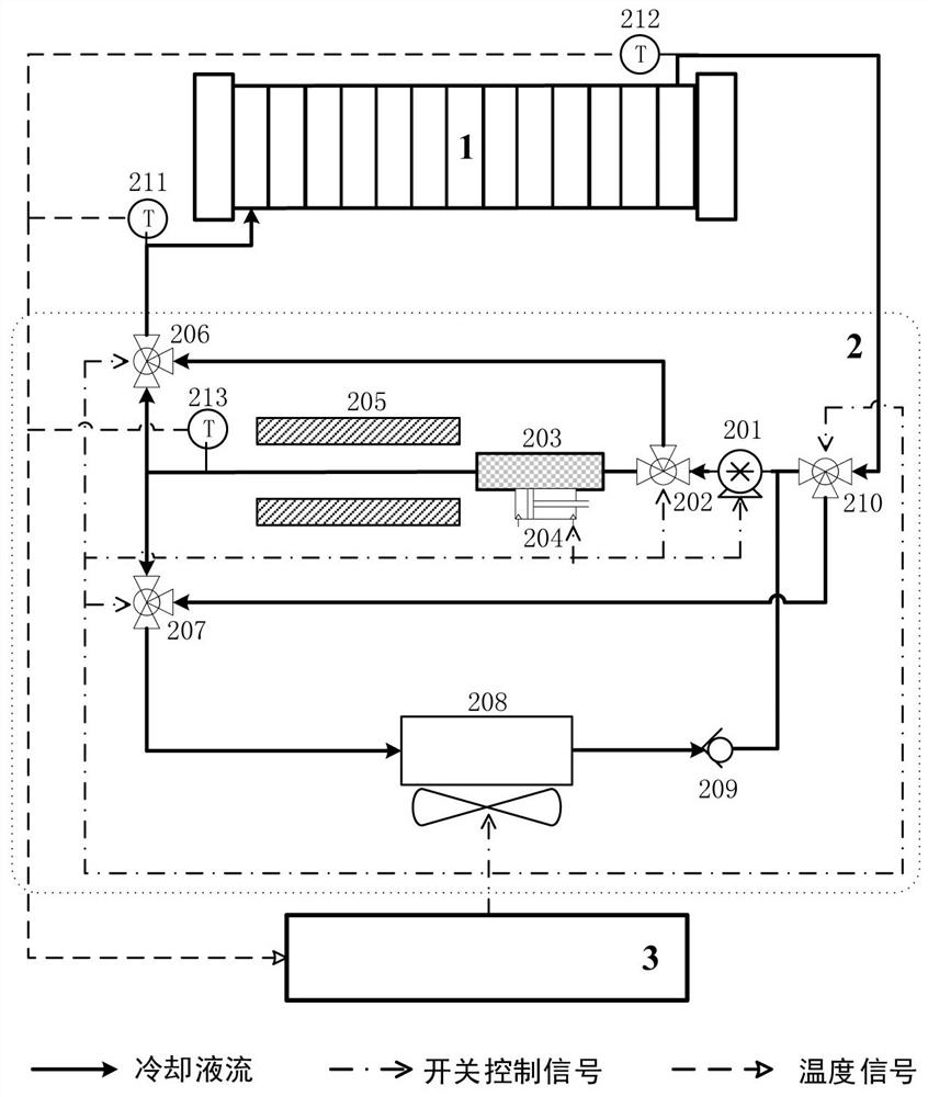
[0065] The thermal management controller 3 uses the coolant temperature of the first temperature sensor 211 or the second temperature sensor 212 in the fuel cell thermal management unit 2 as a reference temperature for subsequent comparison and processing; in another embodiment, the thermal management controller 3 uses The average value of the coolant temperature of the first temperature sensor 211 and the second temperature sensor 212 is used as a parameter for subsequent comparison and processing. Hereinafter, the coolant reference temperature of the first temperature sensor 211 and / or the second temperature sensor 212 in the above-mentioned embodiments is collectively referred to as "fuel cell stack coolant temperature T F ", and the reference temperature of the third temperature sensor 213 is called "magnetic heat storage outlet temperature T M ".

Embodiment 2

[0067] The thermal management controller 3 reads the first threshold temperature T 1 , the second threshold temperature T 2 , where the first threshold temperature T 1 less than the second threshold temperature T 2 , namely T 1 2 . where the first threshold temperature T 1 Set as a temperature in the range of -4°C~0°C; the second threshold temperature T 2 It is set to a temperature in the range of 70° C. to 75° C., which is the optimum temperature for the fuel cell stack 1 to work normally.

[0068] Thermal management controller 3 compares fuel cell stack coolant temperature T F and the first threshold temperature T 1 . When T F 1 When T, the fuel cell thermal management system enters the low-temperature startup mode; F >T 1 , the fuel cell thermal management system enters the normal thermal management mode.

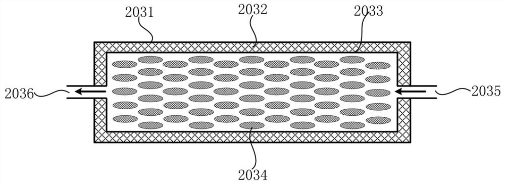
[0069] The invention cleverly uses the magnetocaloric effect of magnetic materials to transfer the heat in the environment to the fuel cell stack by construc...

Embodiment 3

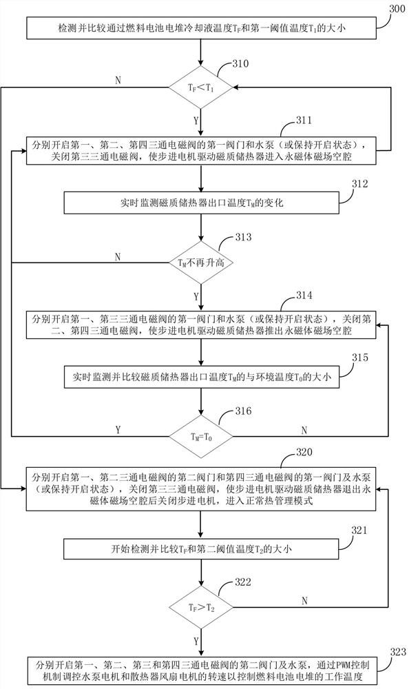
[0071] Embodiments of the present invention also provide a control method for a fuel cell thermal management system based on magnetocaloria, such as image 3 As shown, the method is implemented through the following steps:

[0072] In step 300, the thermal management controller 3 detects the temperature T of the coolant passing through the fuel cell stack 1 F value; in one embodiment, detect the coolant temperature value of the coolant temperature sensor 211 before the fuel cell stack inlet and the coolant temperature sensor 212 after the fuel cell stack outlet, and thus determine the cooling temperature of the fuel cell stack 1 Liquid temperature T F value. Then, compare the fuel cell stack coolant temperature T F and the first threshold temperature T 1 and go to step 310.

[0073] In step 310, thermal management controller 3 detects whether there is T F 1 If yes, go to step 311, otherwise go to step 320.

[0074] In step 311, the thermal management controller 3 respec...


PUM

PropertyMeasurementUnit
Curie pointaaaaaaaaaa

Abstract

The invention relates to a fuel cell thermal management system based on magnetic heat and a control method, the fuel cell thermal management system comprises a fuel cell stack, a fuel cell thermal management unit and a thermal management controller, the thermal management controller is electrically connected with the fuel cell thermal management unit, and the fuel cell thermal management unit is communicated with the fuel cell stack. A permanent magnet and a magnetic mass heat reservoir are connected in series in a circulation loop of the fuel cell heat management unit, a stepping motor drives the magnetic mass heat reservoir to enter and exit a magnetic field cavity of the permanent magnet, magnetization heat release and demagnetization heat absorption are constructed, a fuel cell stack is started at low temperature through heat transfer, the energy consumption is low, irreversible electrochemical active area loss caused by interface separation due to stack icing is avoided, extra energy consumption is avoided, and the utilization rate of the fuel cell is improved.

Description

technical field [0001] The invention belongs to the technical field of fuel cells, and relates to a fuel cell thermal management system and a control method based on magneto-caloric. Background technique [0002] As one of the solutions for vehicle electrification, the large-scale commercialization of fuel cell vehicles still has problems such as high cost, short life, and weak hydrogen infrastructure. Among them, the low-temperature start-up problem of fuel cells is one of the key technical bottlenecks hindering the commercialization of fuel cells, and it is the biggest challenge for fuel cell vehicles to operate in winter. [0003] When the fuel cell is started in a low temperature environment below 0°C without taking any protective measures, the water produced by the reaction will first freeze inside the catalytic layer, resulting in the covering of the active sites of the catalytic layer and the transmission of oxygen. When the catalytic layer is completely covered by i...

Claims


Application Information

Patent Timeline
Patent Type & Authority Applications(China)
IPC IPC(8): H01M8/04007H01M8/04029H01M8/04701
CPCH01M8/04007H01M8/04029H01M8/04701Y02E60/50
Inventor 季孟波
Owner CHINA THREE GORGES NEW ENERGY CO LTD
Why Eureka
Try Eureka