A low-temperature self-starting method for a fuel cell system
A fuel cell system and fuel system technology, applied in the direction of fuel cells, circuits, electrical components, etc., can solve the problems of fuel cell start-up difficulties, and achieve the effects of convenient operation, simple system strategy, and low-temperature start-up
- Summary
- Abstract
- Description
- Claims
- Application Information
AI Technical Summary
Problems solved by technology
Method used
Image

Examples
Embodiment 1
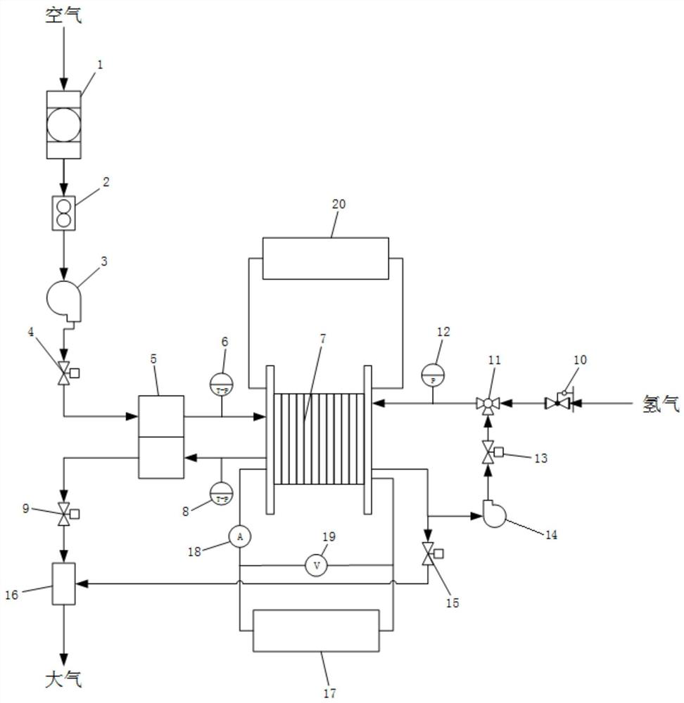
[0048] Such as figure 2 A low-temperature self-starting device for a fuel cell system shown includes a fuel cell stack 7 , an oxidant system, a fuel system, a power control system, and a single-chip voltage monitor 20 .
[0049] Among them, the oxidant system includes an oxidant filter 1, an oxidant flow meter 2, a compressor 3, an oxidant inlet throttle valve 4, an oxidant humidifier 5, an oxidant inlet temperature and pressure integrated sensor 6, an oxidant outlet temperature and pressure integrated sensor 8, an oxidant outlet Gas throttle valve 9, mixed exhaust pipe 16;
[0050] The connection sequence is as follows: the oxidant filter 1, the oxidant flow meter 2, the compressor 3, and the oxidant intake throttle 4 are arranged in series in sequence, and the dry gas inlet and outlet of the oxidant humidifier 5 are respectively connected to the middle of the oxidant intake throttle 4. The outlet of the cooler is connected with the cathode inlet of the fuel cell stack 7, a...
Embodiment 2
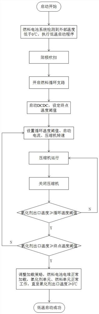
[0077] Such as figure 1 A fuel cell system low-temperature self-starting method based on the fuel cell system low-temperature self-starting device in Embodiment 1 shown, including
[0078] 1) Open the purge branch and perform anode purge on the fuel cell stack 7, then close the purge branch and open the circulation branch;
[0079] 2) Set the cycle temperature threshold, the end point temperature threshold, and the starting current, and adjust the operating speed of the compressor 3 to match the first starting current;
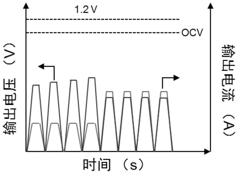
[0080] 3) Start or shut down the compressor 3 intermittently, that is, the compressor 3 runs for 3 seconds, then shuts down for 2 seconds, then restarts and runs for 3 seconds, then shuts down for 2 seconds. This cycle increases the current of the fuel cell stack 7 from zero to the starting current Then reduce to zero, the voltage gradually increases from zero to the starting voltage corresponding to the starting current and then decreases to zero until the o...
Embodiment 3
[0089] In this embodiment, the cycle temperature thresholds are respectively -20°C and -15°C; the end point temperature thresholds are -15°C; the starting currents are 50A and 100A respectively.
[0090]In step 1), during the anode purge process, the purge pressure is 40kPa, and the purge time is 8s;
[0091] After the circulation branch is opened, the anode fuel pressure is 40kPa;
[0092] In step 3), the running time of the compressor 3 is 5s and the closing time is 2.5s during the intermittent startup and shutdown process.
[0093] All the other are with embodiment 2.
PUM
 Abstract
Description
Claims
Application Information
 - R&D
- Intellectual Property
- Life Sciences
- Materials
- Tech Scout
- Unparalleled Data Quality
- Higher Quality Content
- 60% Fewer Hallucinations
Browse by: Latest US Patents, China's latest patents, Technical Efficacy Thesaurus, Application Domain, Technology Topic, Popular Technical Reports.
© 2025 PatSnap. All rights reserved.Legal|Privacy policy|Modern Slavery Act Transparency Statement|Sitemap|About US| Contact US: help@patsnap.com