System and method for purifying product gas of urea hydrolysis

The technology of urea hydrolysis and purification system is applied in the field of preparation of flue gas denitration reducing agent, which can solve the problems of high quality and large energy consumption in heat tracing and thermal insulation construction, achieve simple and convenient ammonia supply system, solve pipeline corrosion, reduce trace The effect of heat and insulation work

Active Publication Date: 2021-12-14
XIAN THERMAL POWER RES INST CO LTD
View PDF15 Cites 0 Cited by
  • Summary
  • Abstract
  • Description
  • Claims
  • Application Information

AI Technical Summary

Problems solved by technology

The current heat tracing methods for the ammonia supply main pipe of the hydrolyzer include steam half-pipe heat tracing, steam jacketed pipe, electric heat tracing, etc. No matter which heat tracing method is used, it will consume a lot of energy. Resulting in higher quality of heat tracing and insulation construction

Method used


Image

  • System and method for purifying product gas of urea hydrolysis

Examples


Embodiment Construction

[0037] The present invention will be further described in detail below in conjunction with specific embodiments, which are explanations of the present invention rather than limitations.

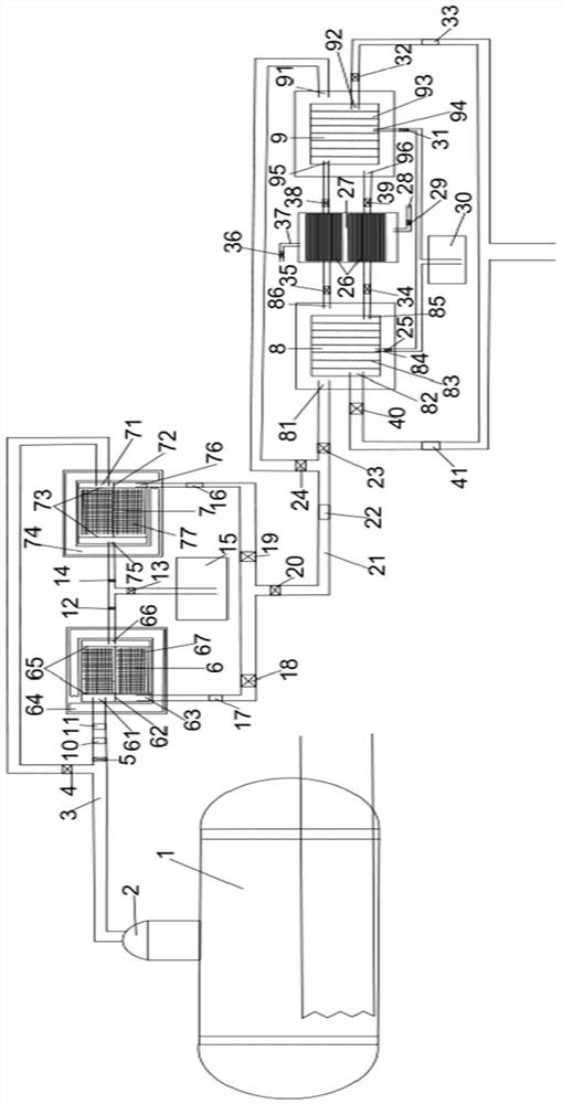
[0038] A urea hydrolysis product gas purification system of the present invention comprises a urea hydrolysis reactor 1, and the reactor is provided with a product gas outlet 2; the product gas outlet 2 is connected to the inlet of the dehydration device through a product gas heat tracing pipeline 3; the outlet of the dehydration device passes through After dehydration, the product gas pipeline 21 is connected to CO 2 The inlet of the absorption and desorption device; the CO 2 The outlet of the absorption and desorption device is connected to the ammonia supply main pipe; that is, the ammonia supply main pipe is connected to the product gas dehydration device and CO 2 Absorption and desorption unit, in which the dehydration unit is located in urea hydrolysis reactor 1 and CO 2 between absor...


PUM


Abstract

The invention discloses a system and a method for purifying produced gas of urea hydrolysis. The system comprises a urea hydrolysis reactor, a dehydration device, a CO2 absorption and desorption device and an ammonia supply mother pipe, wherein a product gas outlet and a heat tracing pipeline are arranged on the urea hydrolysis reactor; the dehydration device comprises at least two dehydration units which are connected in parallel, and an electric heating assembly is arranged in a gap between an outer dehydration shell and an inner dehydration shell; a gas drying agent is arranged in the inner dehydration shell, and the side wall is connected with a product gas inlet pipeline, a product gas outlet pipeline and a water vapor outlet pipeline; the CO2 absorption and desorption device comprises two CO2 removal units and a gas cooling device; the gas channels of the two CO2 removal unit are respectively connected with the gas cooling device and then communicate with the inner absorption shell of the other CO2 removal unit; and the inner absorption shells of the two CO2 removal unit respectively communicate with the ammonia supply mother pipe through corresponding product gas outlet pipelines in the inner shells.

Description

technical field [0001] The invention relates to the field of preparation of a flue gas denitrification reducing agent, in particular to a gas purification system and method for a urea hydrolysis product. Background technique [0002] At present, the denitrification system of coal-fired thermal power plants mostly adopts the selective catalytic reduction (SCR) process. The reducing agent required for the denitrification reaction is ammonia gas, which can be obtained from liquid ammonia, ammonia water and urea. Liquid ammonia and ammonia water are evaporated to produce ammonia. These two ammonia production systems have simple processes, low initial investment, low operating costs and maintenance costs, and are easy to control. However, since liquid ammonia or ammonia water is a toxic and dangerous chemical, and the power plant flue gas The large consumption and storage of liquid ammonia or ammonia water have formed a major source of danger, and the safety risk is very high. I...

Claims


Application Information

Patent Timeline
Patent Type & Authority Applications(China)
IPC IPC(8): C01C1/02B01D53/26B01D53/82B01D53/62B01D53/04
CPCC01C1/024B01D53/26B01D53/82B01D53/62B01D53/04B01D2257/504Y02C20/40Y02P20/151
Inventor 袁壮潘栋杨世极董陈罗志尚桐徐晓涛舒凯李淑宏杨晓刚曹帅峰
Owner XIAN THERMAL POWER RES INST CO LTD
Why Eureka
Try Eureka