Special-shaped contact with self-repairing function

A special-shaped, contact technology, applied in the field of electricity, can solve the problems of reducing flux density, reducing safety factor, reducing service life, etc., to achieve the effect of reducing the voltage drop between contacts, improving connection efficiency and improving service life

Pending Publication Date: 2021-12-03
赵忠扬
View PDF0 Cites 0 Cited by
  • Summary
  • Abstract
  • Description
  • Claims
  • Application Information

AI Technical Summary

Problems solved by technology

[0004] As we all know, direct current is different from alternating current in that it has no zero-crossing point and cannot be switched on and off at zero point, that is, zero voltage and zero current (that is, zero load operation). When controlling the switching of a DC circuit, it needs to be at full voltage and full current. (i.e.: full load operation), that is to say, in the on-off process, as a switch to control it, it needs to withstand the impact of DC current, especially in places with high currents (such as the above-mentioned control series busbar on and off operations) suffer The current impact of the switch will be very strong, because this kind of switch needs to control the on-off DC current is huge, in order to reduce the internal resistance, reduce the loss, and reduce the temperature rise, then it should have a large enough contact area and pressing force. In order to ensure that the dynamic and static contacts can carry a strong current and can work safely and reliably for a long time, otherwise the contact surface will be too small and the current density flowing between the contacts will be too large, which will increase the internal resistance and reduce power consumption. Increase, and make its temperature rise accordingly, if this situation exists and due to the positive temperature coefficient of the metal, as the contact temperature increases, its internal resistance will further increase, and its power consumption will also become exponential As the temperature increases, the temperature rise rate of the contacts will be faster, which forms a vicious cycle of accelerating temperature rise with the temperature rise: to a certain limit, the switch contacts will be melted and burned by the sharply increased high temperature, completely blocking the The circulating working current forms an open circuit. Due to the huge current it carries, a huge amount of energy will be released at the moment when the contact is burned. Under the impact of this energy, the switch will explode instantly and cause an accident, causing (serious) immeasurable damage to the factory. Therefore, in order to ensure the safe and reliable operation of this high-current DC switch, it must have a sufficiently large contact area, a sufficiently large cross-sectional area of ​​the conductor, a reasonable physical structure and a suitable metal properties, in order to effectively reduce the current density passing through it within the allowable range, so that its voltage drop, loss, and temperature rise are always controlled within a safe range, so as to ensure that dangerous accidents will not occur when the switch is closed with a large current load, and the protection It can be safely and smoothly turned on and off in a DC high current environment, but it will face many thorny problems and difficulties while increasing the contact area. If it is not solved, its effectiveness, safety and reliability cannot be guaranteed. In response to this problem, we have developed a set of safe and effective high-current DC switch contact protection mechanism according to the actual situation, which can effectively solve the above situation and avoid fusing accidents

Method used


Image

  • Special-shaped contact with self-repairing function
  • Special-shaped contact with self-repairing function
  • Special-shaped contact with self-repairing function

Examples


specific Embodiment approach 1

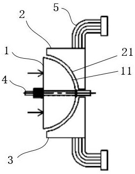
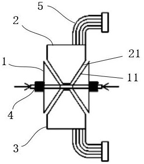
[0027] Such as Figure 1 to Figure 5 As shown, this specific embodiment provides a special-shaped contact with self-repairing function, including an upper connection terminal 2, a lower connection terminal 3 and a contact 1, the contact 1 is provided with a support core rod 4, and the support core rod 4 Pass through the contact 1 and extend into the gap between the upper terminal 2 and the lower terminal 3, the supporting core rod 4 is located between the upper terminal 2 and the lower terminal 3; the contact 1 has a contact contact surface 11. The contact contact surface 11 is a curved surface or a special-shaped slope structure composed of at least two inclined surfaces arranged at an angle. The upper terminal 2 and the lower terminal 3 have a terminal contact surface that is compatible with the contact contact surface 11 21 , the contact contact surface 11 and the terminal contact surface 21 form an engaging structure, and the upper terminal 2 and the lower terminal 3 are c...

specific Embodiment approach 2

[0029] Such as figure 1 As shown, this specific embodiment is a further improvement on the basis of specific embodiment 1, and the improvement points are: contacts 1 are provided on one side of the upper terminal 2 and the lower terminal 3, and the contact surface 11 of the contact is convex. arc-shaped surface, and the protruding direction is the same as the advancing direction of the contact 1 during crimping, and the terminal contact surface 21 is a concave arc-shaped surface. A self-occlusal structure is realized, and the contact 1 has tangential friction during crimping movement. Wherein, the contact 1 is hemispherical, and the contact surface 11 of the contact is hemispherical. In addition, the structure is an internal pressure type, that is, the contact head 1 is touched to complete the crimping action.

specific Embodiment approach 3

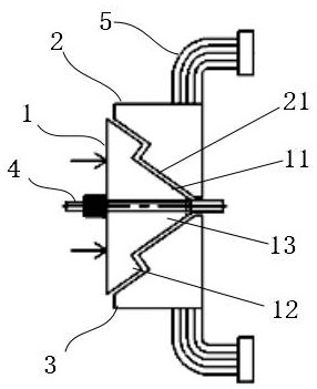
[0030] Such as figure 2 As shown, this specific embodiment is a further improvement on the basis of specific embodiment 1, and the improvement points are: a contact 1 is provided on one side of the upper connection terminal 2 and the lower connection terminal 3, and the contact 1 is provided with an inner engagement part 12 and the outer occlusal portion 13, the outer occlusal portion 13 is an angle structure formed by two inclined surfaces arranged at an angle, the inner occlusal portion 12 is a vertebral structure, the inner occlusal portion 12 extends inwardly and protrudes from the outer occlusal portion 13, and the inner occlusal portion 12 and the protruding direction of the outer bite portion 13 are the same as the propelling direction of the contact 1 during crimping. A self-occlusal structure is realized, and the contact 1 has tangential friction during crimping movement. The conical structure mentioned here can be a flat top (cross-section is conical or other), tha...


PUM


Abstract

The invention provides a special-shaped contact with a self-repairing function, which relates to the field of electricity, and adopts the scheme that the special-shaped contact comprises an upper wiring terminal, a lower wiring terminal and a contact, the contact is provided with a supporting core rod, and the supporting core rod penetrates through the contact and extends into a gap between the upper wiring terminal and the lower wiring terminal; the supporting core rod is located between the upper wiring terminal and the lower wiring terminal. The contact is provided with a contact contact surface, the contact contact surface is a curved surface or a special-shaped inclined surface structure formed by at least two inclined surfaces arranged at an angle, the upper wiring terminal and the lower wiring terminal are provided with terminal contact surfaces matched with the contact contact surface, and the contact contact surface and the terminal contact surfaces form an occlusion structure. A series of defects existing in a common direct-current switch contact and major potential safety hazards easily occurring during operation can be effectively eliminated.

Description

technical field [0001] The invention relates to the field of electrical technology, in particular to a special-shaped contact with self-repairing function. Background technique [0002] With the rapid development of modern industry, there is more and more demand for DC large current on-circuit switches, such as aluminum electrolysis process. According to the current situation of my country's aluminum and power process, the production capacity and scale of the series are continuously increasing, and the series current is also expanding. At present, the new series Some of the currents have reached 670KA, and the number of busbars in the series has also increased to 7. Each busbar has a DC current of nearly 100,000 amperes. Facing such a large amount of current, it is a huge challenge for the on-line control of its load on-off. The design and manufacture of the switch brings great difficulty. [0003] The particularity of direct current, the damage of high current to switch cont...

Claims


Application Information

Patent Timeline
IPC IPC(8): H01H1/06
CPCH01H1/06
Inventor 赵忠扬
Owner 赵忠扬
Why Eureka
Try Eureka