
Radar radiation source signal separation method based on improved variational mode decomposition

A technology of variational modal decomposition and signal separation, which is applied to pattern recognition in signals, computational models, biological models, etc. Poor signal discrimination and other problems, to achieve the effect of fast iterative optimization, avoid mode aliasing, and avoid recognition errors

Pending Publication Date: 2021-11-30
THE 28TH RES INST OF CHINA ELECTRONICS TECH GROUP CORP
View PDF0 Cites 1 Cited by
  • Summary
  • Abstract
  • Description
  • Claims
  • Application Information

AI Technical Summary

Problems solved by technology

[0005] Purpose of the invention: The present invention realizes the effective separation and denoising of mixed radar emitter signals based on variational mode decomposition, which is difficult to reconstruct single-channel underdetermined blind source separation signals, poorly differentiated after separation, and variational mode decomposition For the difficult problem of optimal parameter selection, a radar emitter signal separation method based on improved variational mode decomposition is proposed

Method used


Image

  • Radar radiation source signal separation method based on improved variational mode decomposition
  • Radar radiation source signal separation method based on improved variational mode decomposition
  • Radar radiation source signal separation method based on improved variational mode decomposition

Examples


Embodiment Construction

[0053] The technical solution of the present invention will be clearly and completely described below, and the described embodiments are some embodiments of the present invention, rather than all embodiments:

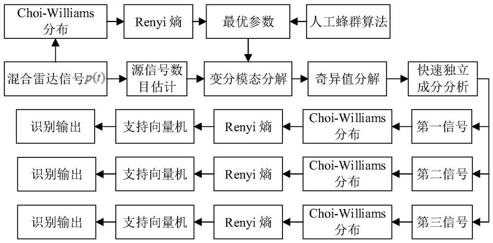
[0054] The embodiment of the present application provides a radar emitter signal separation method based on improved variational mode decomposition, such as figure 1 shown, including the following steps:

[0055] Step 1: Establish the radar emitter signal library, and obtain the additive mixed radar emitter signal p(t);

[0056] Select conventional pulse signal (Continuous Wave, CW), linear frequency modulation signal (Linear Frequency Modulation, LFM), binary phase encoding signal (Binary Phase Shift Keying, BPSK), frequency modulation encoding signal (Costas) and polyphase encoding signal (Frank code Frank, P-phase codes P1, P2, P3, P4) as the research object, the simulation parameters of the radar emitter signal are set as: sampling frequency f s =256MHz, the numbe...


PUM


Abstract

The invention provides a radar radiation source signal separation method based on improved variational mode decomposition. The method comprises the following steps: establishing a radar radiation source signal library of multiple modulation modes; constructing a variational model required by a variational mode decomposition algorithm; extracting the Renyi entropy of the additive hybrid radar signal as a fitness value; calculating optimal parameters of the variational mode decomposition algorithm by applying an artificial bee colony algorithm; decomposing the mixed signal into a virtual multi-channel observation signal through variational mode decomposition; signal reconstruction is realized by means of a singular value decomposition and quick independent component analysis method; extracting a time-frequency domain Renyi entropy of the separated signal as a distinguishing feature; and verifying the signal separation effect by using a support vector machine. According to the method, the additive hybrid radar radiation source signals are separated and recognized, the improved variational mode decomposition method is provided for solving the problems that the number of signals detected by a receiver is large, priori information is little and the recognition effect is poor, quick separation and accurate recognition of the hybrid radar signals are achieved, and a brand new thought is provided for follow-up processing of the hybrid signals.

Description

technical field [0001] The invention belongs to the field of radar radiation source signal separation, in particular to a radar radiation source signal separation method based on improved variational mode decomposition. Background technique [0002] With the increasingly complex electromagnetic environment, the modulation method identification technology of a single radar emitter signal is no longer applicable. Separating and identifying multiple radar signals detected by a receiver has become one of the key technologies in the field of electronic countermeasures. In a real application scenario, real-time processing should be carried out after the radar signal is intercepted, combined with other pulse parameters to confirm the type, quantity and threat level of the radar, and then take necessary protective measures. [0003] Blind source separation can effectively separate mixed signals under the condition of knowing the number of source signals and a small amount of prophet...

Claims


Application Information

Patent Timeline
IPC IPC(8): G06K9/00G06N3/00G06F30/27G01S7/02
CPCG01S7/02G06F30/27G06N3/006G06F2218/02G06F2218/00G06F2218/04G06F2218/08G06F2218/12
Inventor 申良喜孙裔申朱澄澄沈海平刘唐兴黄山良张巍巍吴璇
Owner THE 28TH RES INST OF CHINA ELECTRONICS TECH GROUP CORP
Learn More