Repair device for preventing valve regurgitation
A valve and regurgitation technology, applied in the heart valve, valve annulus, etc., can solve the problems of difficult anchoring, large anchoring parts, and large hemodynamic changes, so as to enhance the anti-reflux effect and fix the position. Safe and effective in improving blood reflux
- Summary
- Abstract
- Description
- Claims
- Application Information
AI Technical Summary
Problems solved by technology
Method used
Image
Examples
Embodiment 1
[0075] The tricuspid valve of the human heart has an anterior leaflet, a posterior leaflet, and a diaphragmatic leaflet. The anterior valve leaflet, posterior valve leaflet and diaphragm valve leaflet are closed when the heart contracts, and when one of the front valve leaflet, posterior valve leaflet and diaphragm valve leaflet cannot close normally in the closed state, valve regurgitation occurs, such as Figures 3a-3c shown.
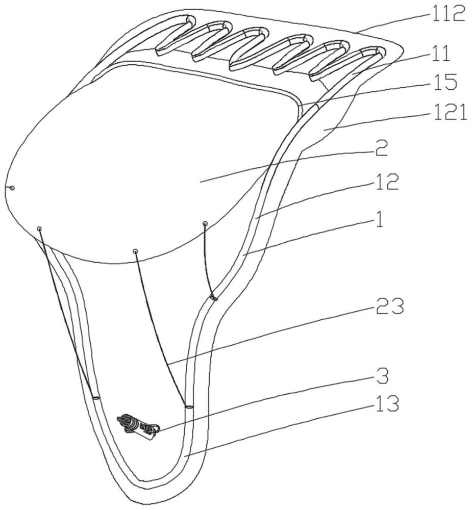
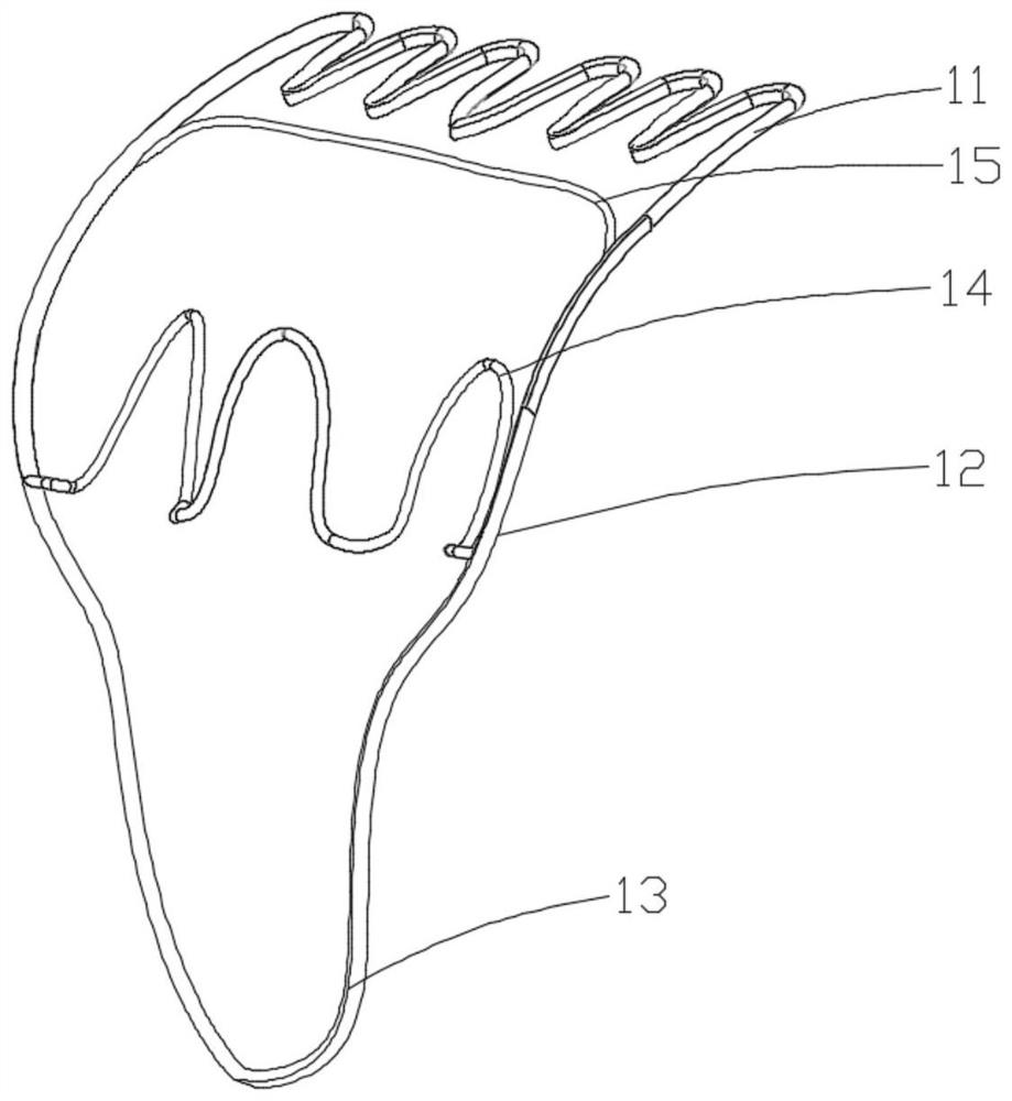
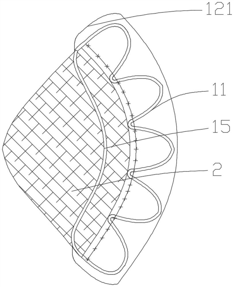
[0076] Such as Figure 1a-1c As shown, a repair device for preventing valve regurgitation includes a mounting bracket 1 , an anti-reflux leaflet prosthesis 2 and an anchor 3 . The proximal end of the mounting bracket 1 is attached to the native valve annulus or cardiac tissue such as atrial tissue, and the distal end of the mounting bracket 1 is fixed on the cardiac tissue such as ventricular tissue through the anchor 3 . The anti-reflux leaflet prosthesis 2 is connected to the mounting bracket 1 in various feasible fixing ways such as fixing, attach...
Embodiment 2
[0114] Embodiment 2 is substantially the same as Embodiment 1. The difference is that in the second embodiment, the repair device is connected to the ventricular tissue through at least two anchors 3, and at least two anchors 3 are separated by a certain distance in the axial direction, such as Figures 6a-6b shown.
[0115] The rest of the structure and idea of the second embodiment are similar to the first embodiment, so no repeated description is given here.
Embodiment 3
[0117] Embodiment three is substantially the same as embodiment one, the difference is that in this embodiment three, such as Figure 7a-7b As shown, in the released state of the prosthetic device, the flaring portion of the mounting bracket, for example, the stop portion 111 of the proximal section 11, can have a configuration similar to a flange (flange), and in the circumferential direction on the native valve The ring extends over the entire circumference of the ring, and the circumferential extension of the limiting portion 111 is at least equal to, and generally larger than, the circumference of the native valve ring, so as to prevent the repair device from moving further toward the ventricle on the one hand. On the other hand, it also contributes to the stable, easy installation and positioning of the repair device at the position of the native valve annulus. This aspect of the third embodiment is different from the first embodiment in detail. In the first embodiment, t...
PUM
 Abstract
Description
Claims
Application Information
 - R&D
- Intellectual Property
- Life Sciences
- Materials
- Tech Scout
- Unparalleled Data Quality
- Higher Quality Content
- 60% Fewer Hallucinations
Browse by: Latest US Patents, China's latest patents, Technical Efficacy Thesaurus, Application Domain, Technology Topic, Popular Technical Reports.
© 2025 PatSnap. All rights reserved.Legal|Privacy policy|Modern Slavery Act Transparency Statement|Sitemap|About US| Contact US: help@patsnap.com


