


Quick Research
Generate reliable direction feasibility study reports for your R&D in just a few steps.

Technical Q&A
Discover and master advanced knowledge NOW. Basics, ideas, possibilities, all at once.

Find Solutions
As an expert in R&D theories, this can generate solutions to your technical problems instantly.

Evaluate Feasibility
Analyze your overall solution with one click, know your potential R&D risks in advance.

Monitor Landscape
Get weekly tech updates, stay abreast of the latest tech innovations and key insights.
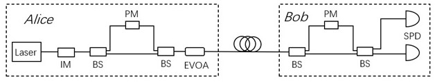
Phase encoding device for quantum key distribution and quantum key distribution system
A quantum key distribution and phase encoding technology, which is applied in the field of phase encoding devices and quantum key distribution systems, can solve the problems of high cost, complexity and high requirements, so as to improve energy utilization, improve security code rate, reduce The effect of cost and complexity
- Summary
- Abstract
- Description
- Claims
- Application Information
AI Technical Summary
Problems solved by technology
Method used
Image

Examples
Embodiment 1
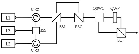
[0038] The structure of the phase encoding device is: the unequal arm polarization interferometer includes a first beam splitter BS1 and a polarization beam combiner PBC, the first optical path selection element OS1 is a first optical switch OSW1, and the second The optical path selection element OS2 is a beam combiner BC, and the phase encoding device further includes a third laser L3, a third beam splitter BS3, a second circulator CIR2, and a third circulator CIR3. The third laser L3, as a seed laser, is connected to the input port of the third beam splitter BS3, and the two output ports of the third beam splitter BS3 are connected to the second circulator CIR2 and the third circulator CIR3 respectively. connected to one port, the second ports of the second circulator CIR2 and the third circulator CIR3 are respectively connected to the first laser L1 and the second laser L2, the third ports of the second circulator CIR2 and the third circulator CIR3 They are respectively con...
Embodiment 2
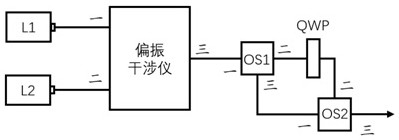
[0047] The structure of the phase encoding device is: the unequal arm polarization interferometer includes a first beam splitter BS1 and a polarization beam combiner PBC, the first optical path selection element OS1 is a fourth beam splitter BS4, and the first beam splitter BS4 The second optical path selection element OS2 is a second optical switch OSW2, the polarization beam combiner PBC includes four ports, and the phase encoding device further includes a fourth laser L4, which is connected to the fourth port of the polarization beam combiner PBC.
[0048] The two-phase encoding process of the embodiment includes:
[0049] The fourth laser L4, as a seed laser, enters the first laser L1 and the second laser L2 through the polarization beam combiner PBC from the opposite direction through the short arm of the unequal-arm polarization interferometer, and performs injection locking on the two respectively. When the first laser L1 is triggered and the second laser L2 is not trig...
Embodiment 3
[0053] The structure of the phase encoding device is: the unequal arm polarization interferometer includes a second beam splitter BS2, a first polarizer POL1, a second polarizer POL2, a first mirror M1, a second mirror M2 and The first circulator CIR1. The polarization-maintaining fiber between the first port of the second beam splitter BS2 and the first laser L1 is fused at 45°, and the polarization-maintaining fiber between the first port of the first circulator CIR1 and the second laser L2 Perform 45° fusion splicing, the second port of the first circulator CIR1 is connected to the second port of the second beam splitter BS2, the third port of the first circulator CIR1 is used as the third port of the unequal arm polarization interferometer port, the first polarizer POL1 is placed at the third port of the second beam splitter BS2, the angle between the polarization direction and the horizontal direction is 0°, and the second polarizer POL2 is placed at the second beam split...
PUM
 Abstract
Description
Claims
Application Information
 - R&D Engineer
- R&D Manager
- IP Professional
- Industry Leading Data Capabilities
- Powerful AI technology
- Patent DNA Extraction
Browse by: Latest US Patents, China's latest patents, Technical Efficacy Thesaurus, Application Domain, Technology Topic, Popular Technical Reports.
© 2024 PatSnap. All rights reserved.Legal|Privacy policy|Modern Slavery Act Transparency Statement|Sitemap|About US| Contact US: help@patsnap.com