
Sulfur hexafluoride gas separation and recovery device

A technology for the separation and recovery of sulfur hexafluoride gas, which is applied in gas/liquid distribution and storage, gas treatment/storage effects, sulfur compounds, etc. It can solve the problems of poor purification accuracy and low recovery efficiency, and achieve fast recovery speed, The effect of improving recovery purity and avoiding pressure rise

Inactive Publication Date: 2021-11-26
STATE GRID HEILONGJIANG ELECTRIC POWER CO LTD ELECTRIC POWER RES INST +1
View PDF7 Cites 2 Cited by
  • Summary
  • Abstract
  • Description
  • Claims
  • Application Information

AI Technical Summary

Problems solved by technology

[0005] The purpose of the present invention is to solve the problems of low recovery efficiency and poor purification precision of existing SF6 gas, and propose a sulfur hexafluoride gas separation and recovery device

Method used


Image

  • Sulfur hexafluoride gas separation and recovery device
  • Sulfur hexafluoride gas separation and recovery device

Examples


specific Embodiment approach 1

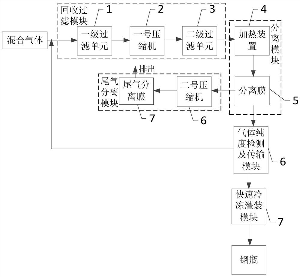
[0034] Embodiment 1: Combining Figure 1 to Figure 2 Illustrating this embodiment, the sulfur hexafluoride gas separation and recovery device described in this embodiment includes a recovery filter module, a separation module, a tail gas separation module, a quick freezing filling device 7 and a gas purity detection and transmission module 6,

[0035] The recovery filter module is used to extract the mixed gas for filtering, and the filtered gas is pressurized and transferred to the separation module;

[0036] The separation module is used to separate the filtered gas into sulfur hexafluoride gas and gas other than sulfur hexafluoride gas. The gas other than sulfur hexafluoride gas enters the tail gas separation module, and the sulfur hexafluoride gas enters the gas purity detection and transmission module 6;

[0037] The tail gas separation module is used to separate gases other than sulfur hexafluoride gas, and the separated gases are discharged separately;

[0038] The ga...

specific Embodiment approach 2

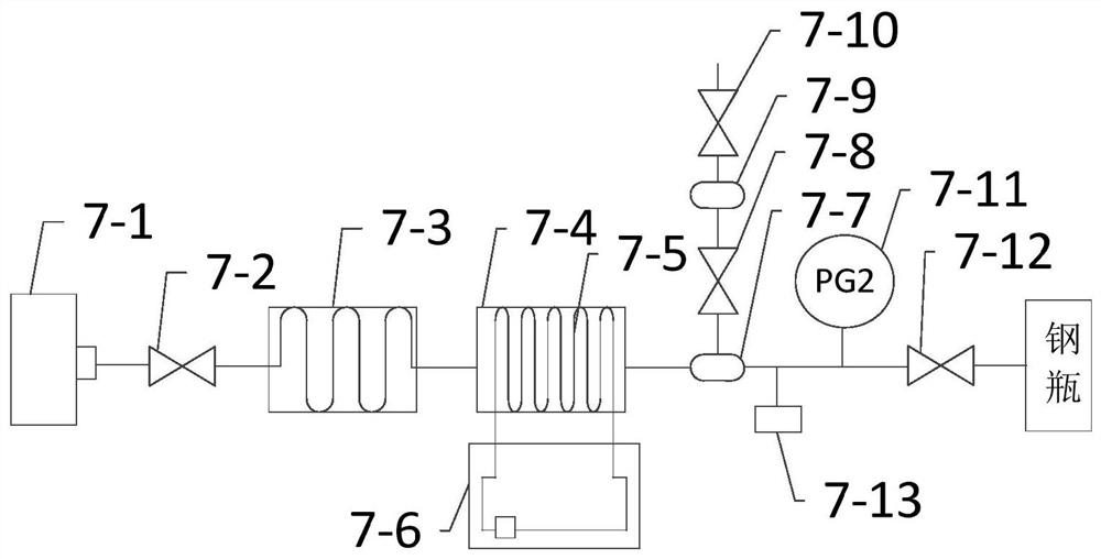
[0043] Embodiment 2: This embodiment further defines the sulfur hexafluoride gas separation and recovery device described in Embodiment 1. In this embodiment, the freezing filling device 7 further includes an exhaust valve 7-10,

[0044] Through the control of the exhaust valve 7-10, the air impurities that are not easily liquefied in the upper tank body 7-9 are discharged.

specific Embodiment approach 3

[0045] Embodiment 3: This embodiment further defines the sulfur hexafluoride gas separation and recovery device described in Embodiment 1. In this embodiment, the freezing filling device 7 further includes pressure gauges 7-11,

[0046] The pressure gauge 7-11 is set on the pipe between the manual valve 7-12 and the pressure transmitter 7-13.


PUM


Abstract

The invention discloses a sulfur hexafluoride gas separation and recovery device and belongs to the field of gas recovery. The sulfur hexafluoride gas separation and recovery device aims to solve the problems of low SF6 gas recovery efficiency and poor purification precision in the prior art. Mixed gas is pumped out by a recovery and filtering module to be filtered, and the filtered gas is pressurized and transferred to a separation module; the separation module is used for separating the filtered gas into sulfur hexafluoride gas and gas except the sulfur hexafluoride gas; a tail gas separation module is used for separating the gas except the sulfur hexafluoride gas, and the separated gas is respectively discharged; a gas purity detection and transmission module detects the purity of the sulfur hexafluoride gas, if the purity of the sulfur hexafluoride gas is larger than or equal to the set purity, the sulfur hexafluoride gas is transmitted to a rapid freezing and filling device, and if the purity of the sulfur hexafluoride gas is smaller than the set purity, the sulfur hexafluoride gas serves as mixed gas and is transmitted to the recovery and filtering module; and the sulfur hexafluoride gas is recovered into a steel cylinder by the rapid freezing and filling device. The device is used for recovering and purifying SF6 gas.

Description

technical field [0001] The invention relates to the recovery of sulfur hexafluoride and belongs to the field of gas recovery. Background technique [0002] Sulfur hexafluoride, the chemical formula is SF6, is a non-toxic, colorless, odorless and non-flammable inert gas. It has become a new generation of ultra-high voltage insulating dielectric materials with its good electrical insulation properties, and is widely used in combined electrical appliances, high-voltage switches, capacitors, and high-voltage cables. Although it is non-toxic and harmless to the human body, it can remain in the atmosphere for up to 3,200 years. Its greenhouse effect is too strong, so it is listed as one of the six major greenhouse gases. For long-term environmental protection and safety considerations, sulfur hexafluoride gas must be recycled reasonably and correctly. [0003] At present, during the recovery process, the maintenance personnel extract the gas from the substation equipment, put it...

Claims


Application Information

Patent Timeline
Patent Type & Authority Applications(China)
IPC IPC(8): F17C5/04F17C13/02F17C13/04C01B17/45
CPCF17C5/04F17C13/02F17C13/04C01B17/453F17C2221/03F17C2250/03F17C2265/012F17C2265/015Y02P20/10
Inventor 张亮张健付丽君关艳玲迟敬元卫兵王晗张航张德文梁建权王悦
Owner STATE GRID HEILONGJIANG ELECTRIC POWER CO LTD ELECTRIC POWER RES INST
Learn More