


Quick Research
Generate reliable direction feasibility study reports for your R&D in just a few steps.

Technical Q&A
Discover and master advanced knowledge NOW. Basics, ideas, possibilities, all at once.

Find Solutions
As an expert in R&D theories, this can generate solutions to your technical problems instantly.

Evaluate Feasibility
Analyze your overall solution with one click, know your potential R&D risks in advance.

Monitor Landscape
Get weekly tech updates, stay abreast of the latest tech innovations and key insights.
Laser cutting equipment for decoration plates
A laser cutting and equipment technology, applied in laser welding equipment, welding equipment, metal processing equipment, etc., can solve the problems of increasing the safety performance of the device, easy to stick on the cutting table, distraction, etc., to achieve convenient removal and improve quality Effect
- Summary
- Abstract
- Description
- Claims
- Application Information
AI Technical Summary
Problems solved by technology
Method used
Image

Examples
Embodiment 1
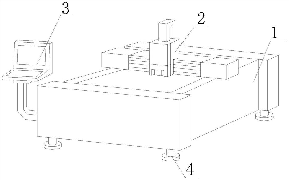
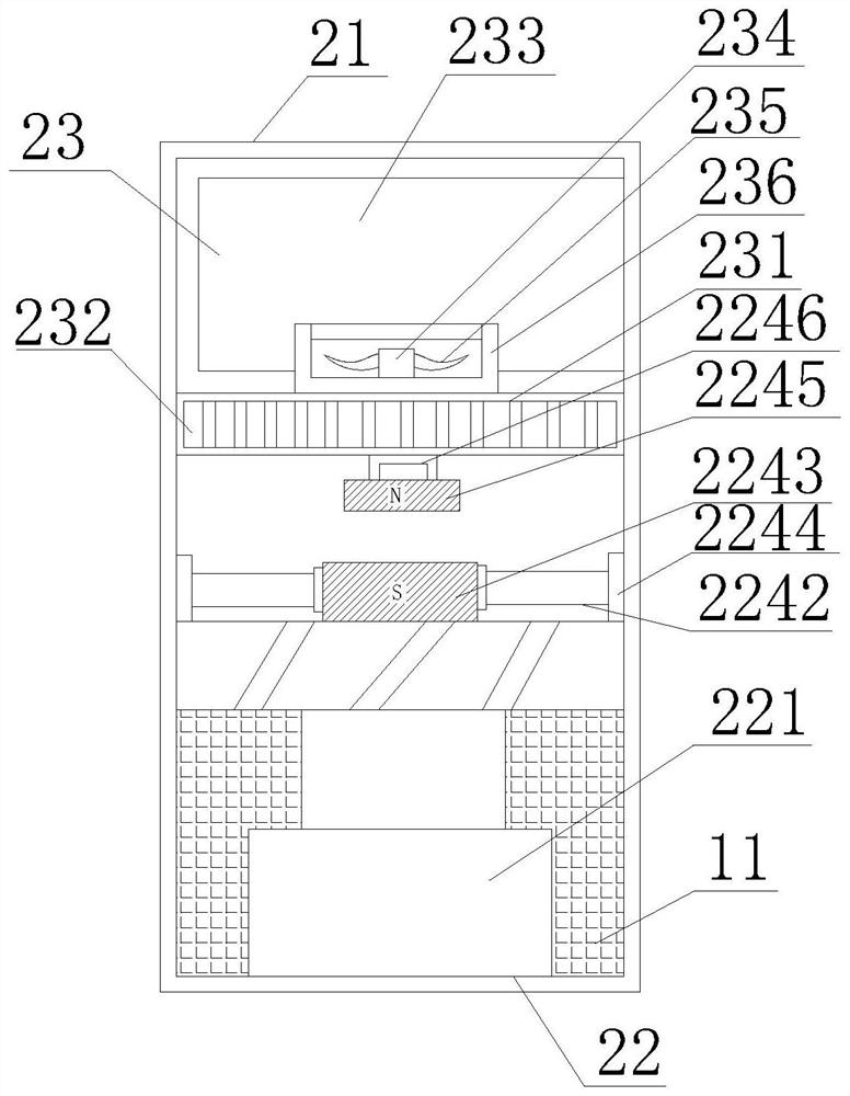
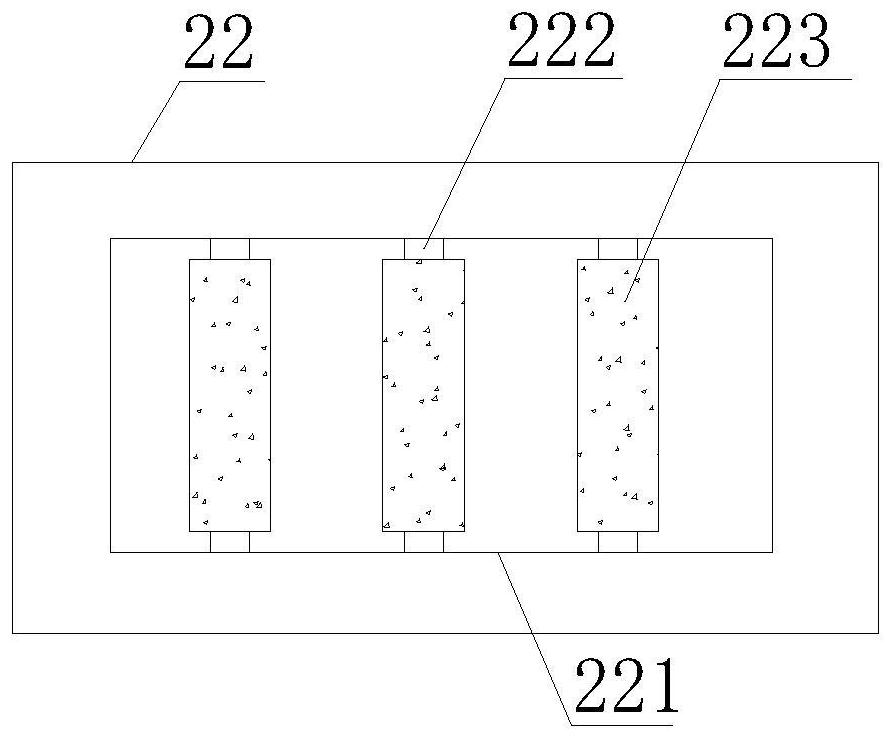
[0043] Such as Figure 1-7As shown, the present invention provides a kind of laser cutting equipment of decoration plate, comprises processing table 1, cutting device 2, console 3 and support column 4, and the both sides of processing table 1 are fixedly installed with protective block 10, and processing table 1 A cutting device 2 is movable on the top, a console 3 is fixedly installed on the side of the processing table 1, a support column 4 is fixedly installed on the bottom of the processing table 1, a cleaning device 21 is fixedly installed inside the cutting device 2, and a cleaning device 21 is fixedly installed on the side There is a grinding device 11, the inside of the processing table 1 includes a clamping device 14 and a pushing device 15, the cleaning device 21 includes a suction device 22 and a collection device 23, the suction device 22 includes a suction port 221, and the top of the suction port 221 is fixedly installed There is a rotating ring 2242, a rotating ...
Embodiment 2
[0046] Such as Figure 1-7 Shown, on the basis of embodiment 1, the present invention provides a kind of technical scheme: preferably, collecting device 23 comprises filter screen 231, and the inside of filter screen 231 is provided with filter hole 232, and the top of filter screen 231 is fixedly installed with A filter bag 233 , a rotating shaft 234 is fixedly installed inside the filter bag 233 , a fan blade 235 is fixedly installed outside the rotating shaft 234 , and a fan housing 236 is fixedly installed outside the fan blade 235 .
[0047] In this embodiment, the rotating shaft 234 is energized to rotate, so that the fan blade 235 rotates, so that the suction port 221 is reversed, so that the polished waste enters the inside of the collecting device 23, and then the rotating column 222 The adhesion block 223 on the top is adhered, so that the waste on the processing table is removed, thereby conveniently removing the waste, which is conducive to reducing manual cleaning...
Embodiment 3
[0049] Such as Figure 1-7 As shown, on the basis of Embodiment 1, the present invention provides a technical solution: preferably, the clamping device 14 includes a snap-in block 141, and the side of the snap-in block 141 is movably socketed on the protective block 10, snap-in The other side of the block 141 is fixedly equipped with a hydraulic rod 142, and the side of the hydraulic rod 142 away from the clamping block 141 is fixedly installed with an extrusion plate 143, and the top of the extrusion plate 143 is fixedly equipped with an air bag 1431, and the top of the air bag 1431 A buffer stage 1432 is fixedly installed, and a friction block 1433 is fixedly installed on the top of the buffer stage 1432. The push-out device 15 includes a baffle 151, and the bottom of the baffle 151 is fixedly equipped with a buffer column 152, and the bottom of the buffer column 152 is fixedly installed with a A telescopic column 1521 is fixedly installed inside the hydraulic column 153 and...
PUM
 Abstract
Description
Claims
Application Information
 - R&D Engineer
- R&D Manager
- IP Professional
- Industry Leading Data Capabilities
- Powerful AI technology
- Patent DNA Extraction
Browse by: Latest US Patents, China's latest patents, Technical Efficacy Thesaurus, Application Domain, Technology Topic, Popular Technical Reports.
© 2024 PatSnap. All rights reserved.Legal|Privacy policy|Modern Slavery Act Transparency Statement|Sitemap|About US| Contact US: help@patsnap.com