Deep ultraviolet LED chip and manufacturing method thereof

An LED chip, deep ultraviolet technology, applied in electrical components, circuits, semiconductor devices, etc., can solve the problems of reducing hole concentration, affecting the luminous amount of deep ultraviolet LED chips, reducing deep ultraviolet light absorption, etc., to reduce the contact barrier. , The effect of increasing light extraction efficiency and increasing light extraction efficiency

Pending Publication Date: 2021-11-02
XIAMEN SILAN ADVANCED COMPOUND SEMICON CO LTD +1
View PDF6 Cites 0 Cited by
  • Summary
  • Abstract
  • Description
  • Claims
  • Application Information

AI Technical Summary

Problems solved by technology

[0002] In the deep ultraviolet LED chip (Light-Emitting Diode, light-emitting diode), in order to make the P-type semiconductor layer obtain better ohmic contact effect and higher hole concentration, it is necessary to grow another layer of p- on the P-type semiconductor layer. The GaN layer, however, the p-GaN layer will absorb a large amount of deep ultraviolet light, which seriously affects the light emission of the deep ultraviolet LED chip
Although the absorption of deep ultraviolet light can be reduced by thinning the p-GaN layer, the hole concentration will be significantly reduced

Method used


Image

  • Deep ultraviolet LED chip and manufacturing method thereof
  • Deep ultraviolet LED chip and manufacturing method thereof
  • Deep ultraviolet LED chip and manufacturing method thereof

Examples


Embodiment Construction

[0062] Hereinafter, the present invention will be described in more detail with reference to the accompanying drawings. In the various figures, identical elements are indicated with similar reference numerals. For the sake of clarity, various parts in the drawings have not been drawn to scale. Also, some well-known parts may not be shown. For the sake of simplicity, the semiconductor structure obtained after several steps can be described in one figure.

[0063] It should be understood that when describing the structure of a device, when a layer or a region is referred to as being "on" or "over" another layer or another region, it may mean being directly on another layer or another region, or Other layers or regions are also included between it and another layer or another region. And, if the device is turned over, the layer, one region, will be "below" or "beneath" the other layer, another region.

[0064] If it is intended to describe the situation of being directly on a...


PUM

PropertyMeasurementUnit
thicknessaaaaaaaaaa
thicknessaaaaaaaaaa
thicknessaaaaaaaaaa

Abstract

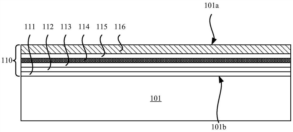
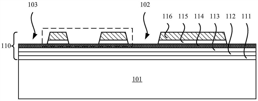
The invention discloses a deep ultraviolet LED chip and a manufacturing method thereof, and the deep ultraviolet LED chip comprises an epitaxial structure which is provided with a first surface and a second surface which are opposite to each other, the epitaxial structure comprises a P-type semiconductor layer, an N-type semiconductor layer and a multi-quantum well layer clamped between the P-type semiconductor layer and the N-type semiconductor layer, and the P-type semiconductor layer is exposed on the first surface of the epitaxial structure; and a hole compensation layer of the P-type semiconductor layer is located on the first surface of the epitaxial structure. According to the deep ultraviolet LED chip, the hole compensation layer of the P-type semiconductor layer is utilized to ensure that the P-type semiconductor layer obtains relatively high hole concentration, and meanwhile, the absorption of an internal structure of the deep ultraviolet LED chip to deep ultraviolet light is reduced.

Description

technical field [0001] The present application relates to the technical field of semiconductor manufacturing, and more specifically, to a deep ultraviolet LED chip and a manufacturing method thereof. Background technique [0002] In the deep ultraviolet LED chip (Light-Emitting Diode, light-emitting diode), in order to make the P-type semiconductor layer obtain better ohmic contact effect and higher hole concentration, it is necessary to grow another layer of p- on the P-type semiconductor layer. The GaN layer, however, the p-GaN layer will absorb a large amount of deep ultraviolet light, which seriously affects the light emission of the deep ultraviolet LED chip. Although the absorption of deep ultraviolet light can be reduced by thinning the p-GaN layer, the hole concentration will be significantly reduced. [0003] Therefore, it is necessary to improve the deep ultraviolet LED chip and its manufacturing method, hoping to reduce the absorption of deep ultraviolet light by...

Claims


Application Information

Patent Timeline
Patent Type & Authority Applications(China)
IPC IPC(8): H01L33/06H01L33/14H01L33/24H01L33/46H01L33/00
CPCH01L33/06H01L33/14H01L33/46H01L33/24H01L33/007
Inventor 范伟宏毕京锋郭茂峰李士涛马新刚赵进超
Owner XIAMEN SILAN ADVANCED COMPOUND SEMICON CO LTD
Why Eureka
Try Eureka