
Heat dissipation device provided with heat dissipation fan and used for electrical device

A heat dissipation device and heat dissipation fan technology, which is applied to the structural parts of electrical equipment, electrical components, and decoration through conduction and heat transfer, can solve the problems of slow heat transfer, uneven heat transfer, low heat dissipation efficiency, etc., and achieve structural stability. Strong adaptability, reduce heat accumulation, improve heat conduction efficiency

Pending Publication Date: 2021-10-12
江苏矽美科散热科技有限公司
View PDF0 Cites 0 Cited by
  • Summary
  • Abstract
  • Description
  • Claims
  • Application Information

AI Technical Summary

Problems solved by technology

[0002] Commonly used electrical equipment such as solid-state hard drives, optical modules, laser TVs, communication base stations, TVs, electric vehicles, etc., in order to improve the overall performance of these electrical equipment, there are chips inside, and the chip is the heat generated in the entire electrical equipment. One of the largest component structures, the heat needs to be dissipated in time, otherwise it will cause the electrical equipment to overheat, affect the working performance of the electrical equipment, and even lead to some safety accidents
[0003] In the existing technology, the heat dissipation structure of the chip is generally an aluminum extruded structure, but the heat dissipation efficiency of the traditional aluminum extrusion heat dissipation structure is low, the heat transfer is slow, the thermal resistance is large, and the heat transfer is uneven, so that the heat cannot be dissipated to the outside of the electrical equipment in time , so the temperature inside the electrical equipment will rise rapidly, and the performance will drop sharply. Therefore, it is necessary to improve the traditional aluminum extrusion heat dissipation structure and improve the heat dissipation effect of the chip in the electrical equipment.

Method used


Image

  • Heat dissipation device provided with heat dissipation fan and used for electrical device
  • Heat dissipation device provided with heat dissipation fan and used for electrical device
  • Heat dissipation device provided with heat dissipation fan and used for electrical device

Examples


Embodiment 1

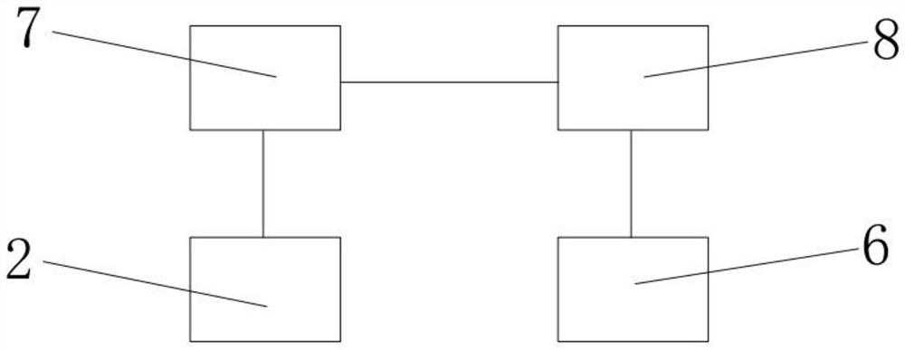
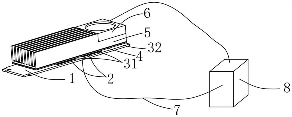
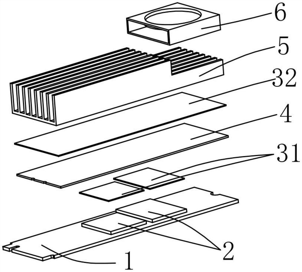
[0031] Such as Figure 1-3 As shown, the heat dissipation device for electrical equipment provided with a heat dissipation fan includes a body 1 and a chip 2 arranged above the body 1. On the other side of the chip 2 relative to the body 1, a first heat-conducting silicone gasket 31, a heat dissipation The element 4, the second heat-conducting silicone gasket 32, the heat dissipation module 5 and the heat dissipation fan 6; wherein the heat dissipation element 4 is a heat pipe or a vapor chamber, and the heat dissipation fan 6 is a variable-speed fan.

[0032] In this embodiment 1, the heat dissipation module 5 is an aluminum extrusion, and the heat dissipation fan 6 is fixed on the aluminum extrusion. Specifically, the heat dissipation fan 6 can be fixed on the upper surface of the heat dissipation module 5 through heat-conducting silica gel or screws.

[0033] The chip 2 has a cuboid sheet structure, the pins of the chip 2 are welded on the body 1, the size of the first the...

Embodiment 2

[0038] In this embodiment 2, the heat dissipation principle of the heat dissipation device for electrical equipment provided with a heat dissipation fan is the same as that of embodiment 1, as figure 1 Shown; The structure of heat sink is basically the same as embodiment 1, as Figure 4 and 5 Shown, in this embodiment 2:

[0039] The heat dissipation device for electrical equipment provided with a heat dissipation fan includes a body 1 and a chip 2 arranged above the body 1. On the other side of the chip 2 relative to the body 1, a thermally conductive silicone gasket 3, a heat dissipation module 5 and a heat dissipation module are sequentially provided. A fan 6; wherein the cooling element 4 is a heat pipe or a vapor chamber, and the cooling fan 6 is a variable-speed fan.

[0040] In this embodiment 2, the heat dissipation module 5 is an aluminum extrusion, and the heat dissipation fan 6 is fixed on the aluminum extrusion. Specifically, the heat dissipation fan 6 can be fi...


PUM


Abstract

The invention discloses a heat dissipation device provided with a heat dissipation fan and used for an electrical device, and belongs to the technical field of heat dissipation. The electrical device comprises a body and a chip fixed on the body, and a heat conduction silica gel gasket, a heat dissipation module and the heat dissipation fan are sequentially arranged at the other side, opposite to the body, of the chip; the heat dissipation device further comprises a PLC and a thermocouple, a temperature sensing probe of the thermocouple is fixed to the surface of the chip, and the PLC is electrically and separately connected with the thermocouple and the heat dissipation fan. According to the present invention, the heat conduction silica gel gasket, the heat dissipation module and the heat dissipation fan are combined for use, compared with a traditional aluminum extrusion heat dissipation structure, under the same conditions, the heat dissipation efficiency is high, heat dissipation is uniform, the heat accumulation can be effectively reduced, and the heat in a high-temperature area can be rapidly conducted out and transmitted to the heat dissipation module, and the heat on the heat dissipation module is taken away through the heat dissipation fan, so that the heat dissipation efficiency is higher, and the application field is wider.

Description

technical field [0001] The invention belongs to the technical field of heat dissipation, and in particular relates to a heat dissipation device for electrical equipment provided with a heat dissipation fan. Background technique [0002] Commonly used electrical equipment such as solid-state hard drives, optical modules, laser TVs, communication base stations, TVs, electric vehicles, etc., in order to improve the overall performance of these electrical equipment, there are chips inside, and the chip is the heat generated in the entire electrical equipment. One of the largest parts structures, the heat needs to be dissipated in time, otherwise it will cause the electrical equipment to overheat, affect the working performance of the electrical equipment, and even lead to some safety accidents. [0003] In the existing technology, the heat dissipation structure of the chip is generally an aluminum extruded structure, but the heat dissipation efficiency of the traditional aluminu...

Claims


Application Information

Patent Timeline
Patent Type & Authority Applications(China)
IPC IPC(8): H05K7/20
CPCH05K7/2039H05K7/20145H05K7/20209H05K7/20336
Inventor 刘成彬赵泽强
Owner 江苏矽美科散热科技有限公司
Learn More