A flue gas waste heat recovery device

A technology of recycling device and waste heat of flue gas, applied in exhaust gas device, indirect heat exchanger, type of heat exchanger, etc., can solve the problems of dust accumulation in heat conduction pipe, affecting the heat conduction performance of heat conduction pipe, and high boiler cost, so as to ensure heat conduction. performance, improved utilization

Active Publication Date: 2022-05-17
宁波久丰热电有限公司
View PDF0 Cites 0 Cited by
  • Summary
  • Abstract
  • Description
  • Claims
  • Application Information

AI Technical Summary

Problems solved by technology

[0004] In view of the above-mentioned related technologies, the inventor believes that there are the following defects: after the above-mentioned flue gas waste heat recovery device works for a long time, the flue gas will cause dust accumulation on the heat transfer tube, thereby affecting the thermal conductivity of the heat transfer tube
However, due to the high cost of shutting down the boiler, the boiler will only be shut down once after a long period of time, so that the heat transfer tube will need to be repaired once after a long period of time, which needs to be improved

Method used


Image

  • A flue gas waste heat recovery device
  • A flue gas waste heat recovery device
  • A flue gas waste heat recovery device

Examples


Embodiment Construction

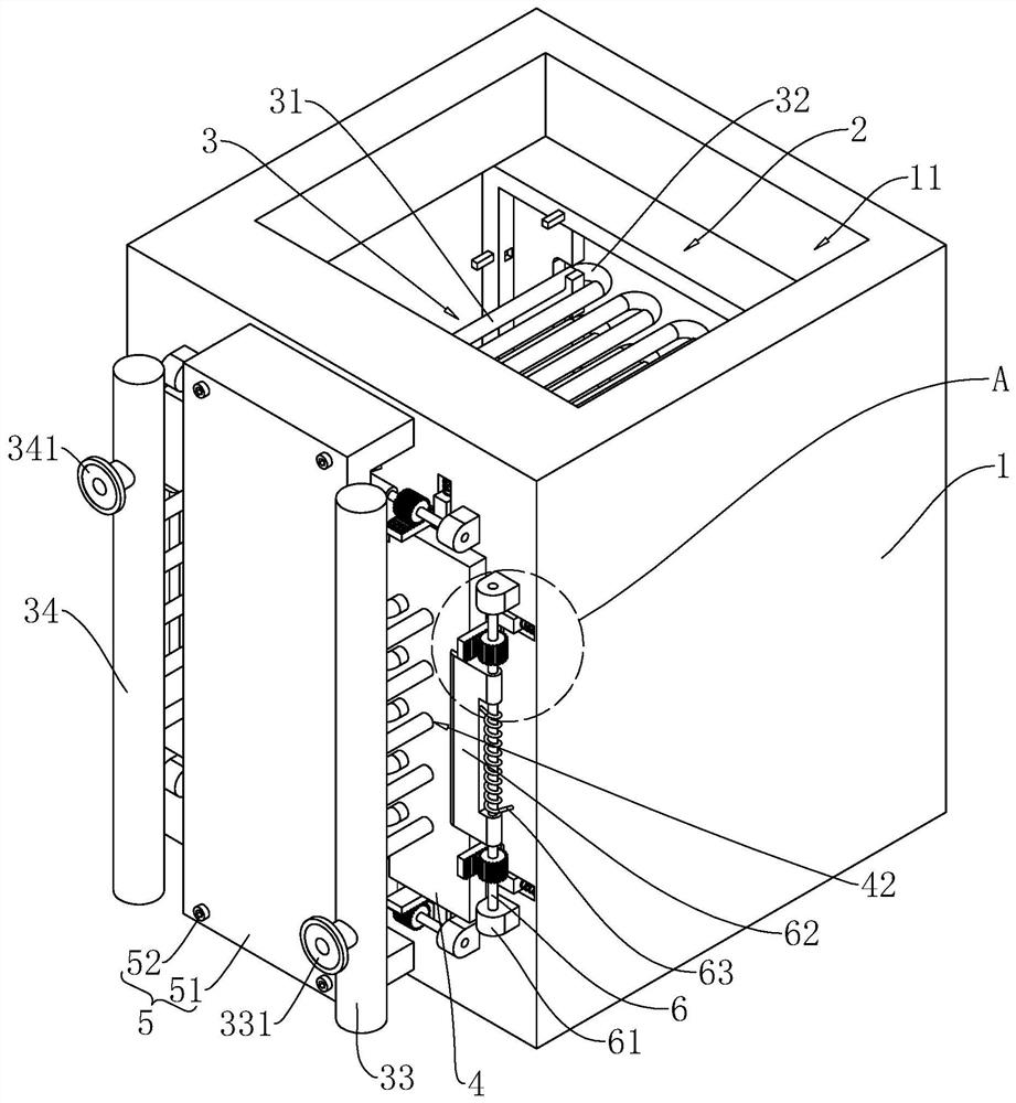
[0038] The following is attached Figure 2-8 The application is described in further detail.

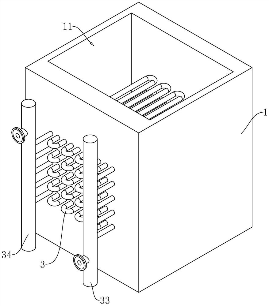
[0039] The embodiment of the present application discloses a flue gas waste heat recovery device. refer to figure 2 The flue gas waste heat recovery device includes a box body 1 with an inner cavity, a smoke hood 2 slidably arranged in the inner cavity of the box body 1, five heat pipes 3 detachably connected to the smoke hood 2, and a heat pipe connected to the heat pipe 3, the water inlet pipe 33 and the water outlet pipe 34, the inspection cover 4 detachably connected to the casing 1, and the fixing mechanism 5 connected to the casing 1.

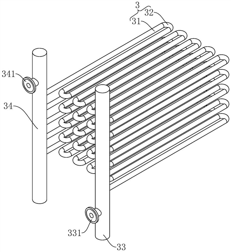
[0040] refer to figure 2 , image 3 , the two ends of the heat pipe 3 are respectively welded and fixed with the water inlet pipe 33 and the water outlet pipe 34, and the inner chamber of the heat pipe 3 is connected with the inner chambers of the water inlet pipe 33 and the water outlet pipe 34. The heat pipes 3 are arranged in a serpent...


PUM


Abstract

This application discloses a flue gas waste heat recovery device, which includes a box body with an inner cavity, a water inlet pipe, a water outlet pipe, and a heat conduction pipe. The box body is provided with a smoke exhaust hole that communicates with the boiler flue. The two ends of the heat pipe are respectively connected with the water inlet pipe and the water outlet pipe. The box is provided with an inspection port connected with the inner cavity of the box. The inspection port is used for the heat pipe to pass through. The box body is detachable. An inspection cover for covering the inspection opening is connected, and a smoke-blocking cover for covering the inspection opening is detachably connected to the heat-conducting pipe, and the smoke-blocking cover slides in the inner cavity of the box. A plurality of bent pipes are used to connect adjacent straight pipes, the inspection cover is provided with sliding holes for the straight pipes to slide, and the box body is connected with a fixing mechanism to limit the sliding of the straight pipes. The present application has the effect of being able to overhaul the heat transfer tube without shutting down the boiler.

Description

technical field [0001] The present application relates to the technical field of thermal power generation and energy saving, in particular to a flue gas waste heat recovery device. Background technique [0002] A thermal power plant is a factory that uses combustibles as fuel to produce electrical energy. In the process of thermal power generation, coal combustion produces a large amount of flue gas. By installing a flue gas waste heat recovery device at the boiler smoke port, the waste heat of the flue gas can be recovered to heat domestic water or boiler water, which improves the utilization rate of resources. [0003] related technologies, such as figure 1 A flue gas waste heat recovery device is shown, which includes a box body 1 provided with a smoke exhaust hole 11, a water inlet pipe 33, a water outlet pipe 34, and a heat transfer pipe 3 whose two ends are respectively connected to the water inlet pipe 33 and the water outlet pipe 34, The exhaust hole 11 is used to ...

Claims


Application Information

Patent Timeline
Patent Type & Authority Patents(China)
IPC IPC(8): F23J15/06F23J13/00F28D7/08
CPCF23J15/06F23J13/00F28D7/082Y02E20/30
Inventor 卜金星张斌孙乐天孙博昂
Owner 宁波久丰热电有限公司
Why Eureka
Try Eureka