Signal conversion method and system for accelerator pedal of hybrid electric vehicle
A hybrid vehicle, accelerator pedal technology, applied in hybrid vehicles, the arrangement of power plant control mechanisms, motor vehicles and other directions
- Summary
- Abstract
- Description
- Claims
- Application Information
AI Technical Summary
Problems solved by technology
Method used
Image
Examples
Embodiment 1
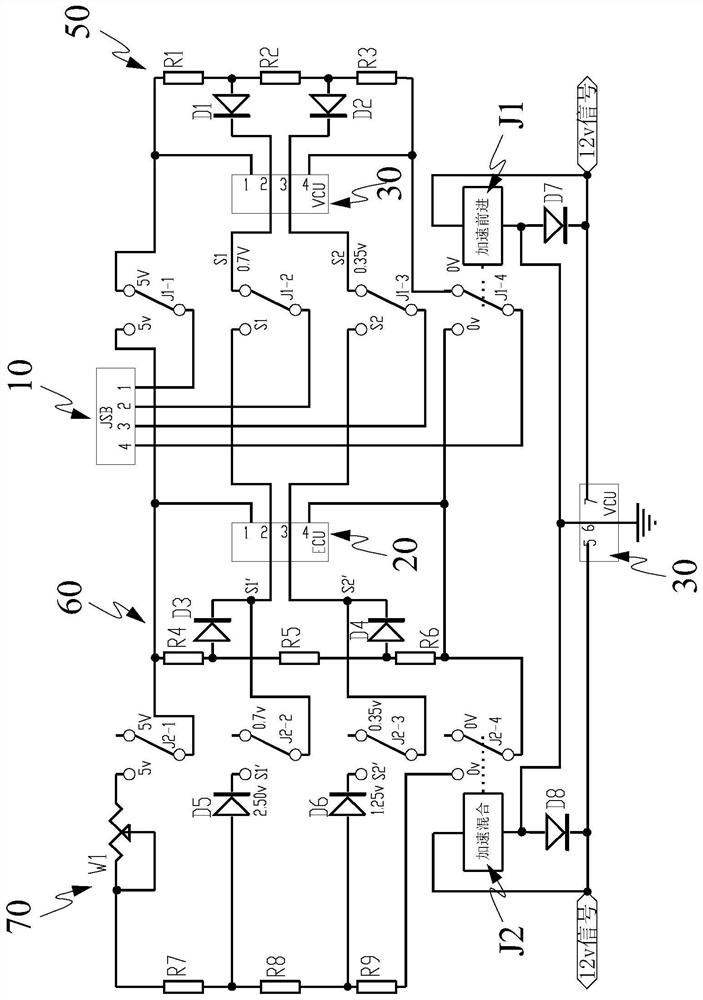
[0055] Such as Figure 1~2 As shown, a signal conversion method of an accelerator pedal of a hybrid vehicle includes an accelerator pedal 10, an ECU20 and a VCU30, wherein:
[0056] It turns out that the accelerator pedal has multiple contacts, and the two positive poles are combined to a common positive pole of 5V, the two negative poles are combined to be changed to a common negative pole of 0V, and the signal S1 and signal S2 remain unchanged; thus, the accelerator pedal has four signals contact;
[0057] It turns out that the ECU has multiple contacts, and the two positive poles are merged to a common positive pole of 5V, the two negative poles are combined to be changed to a common negative pole of 0V, and ECU-2 and ECU-3 remain unchanged; thus, the ECU has four signals contacts,
[0058] It turns out that the VCU has multiple contacts, and the two positive poles are merged into a common positive pole 5V, and the two negative poles are combined into a common negative po...
Embodiment 2
[0062] As an improvement of Embodiment 1 of the present invention, such as figure 1 Shown:
[0063] The line signal switching device adopts an acceleration relay J1 and an acceleration hybrid relay J2, and the VCU30 controls the acceleration relay J1 and the acceleration hybrid relay J2;
[0064] When only driving the motor, the signal contact of the accelerator pedal communicates with the signal contact of the VCU through the acceleration forward relay J1;
[0065] When only the engine is driving, the signal contact of the accelerator pedal communicates with the signal contact of the ECU through the acceleration forward relay J1;
[0066] When the driving motor and the engine are driven in a mixed manner, the accelerator pedal signal contact communicates with the signal contact of the VCU through the accelerator forward relay J1; and the accelerator hybrid relay J2 transmits the analog accelerator pedal opening signal to the signal contact of the ECU.
[0067] A system impl...
Embodiment 3
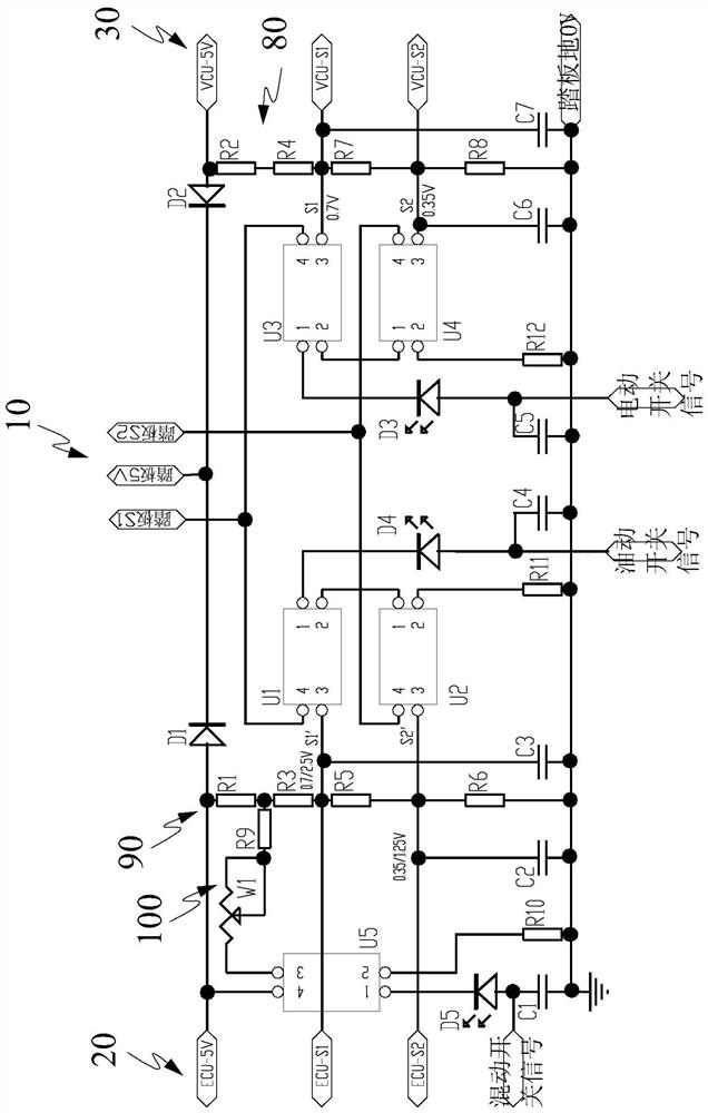
[0097] As an improvement of Embodiment 1 of the present invention, such as figure 2 Shown:
[0098] D1-D2 represent voltage isolation diodes, and D3-D5 represent light-emitting indicator diodes.
[0099] The line signal switching device is five optocoupler tubes, which are optocoupler tube one U1, optocoupler tube two U2, optocoupler tube three U3, optocoupler tube four U4, and optocoupler tube five U5;
[0100] Receive the electric switch signal, that is: when only the drive motor is driven, the signal contact of the accelerator pedal is connected to the signal contact of the VCU through the photocoupler three U3 and the photocoupler four U4;
[0101] Receive the oil switch signal, that is, when the engine is only driven, the signal contact of the accelerator pedal is connected to the signal contact of the ECU through the optocoupler tube 1 U1 and optocoupler tube 2 U2;
[0102] Receive the hybrid switch signal, that is: when the driving motor and the engine are mixed driv...
PUM
 Abstract
Description
Claims
Application Information
 - Generate Ideas
- Intellectual Property
- Life Sciences
- Materials
- Tech Scout
- Unparalleled Data Quality
- Higher Quality Content
- 60% Fewer Hallucinations
Browse by: Latest US Patents, China's latest patents, Technical Efficacy Thesaurus, Application Domain, Technology Topic, Popular Technical Reports.
© 2025 PatSnap. All rights reserved.Legal|Privacy policy|Modern Slavery Act Transparency Statement|Sitemap|About US| Contact US: help@patsnap.com


