
Automobile hub machining process

A processing technology and technology of automobile wheel hubs, applied in the direction of wheel hubs, rims, vehicle parts, etc., can solve the problems of thin rim wall spinning, no mold sticking, etc., and achieve the effect of reducing the weight of the whole vehicle, clear steering, and increasing cruising range.

Active Publication Date: 2021-08-31
重庆市超群工业股份有限公司
View PDF26 Cites 4 Cited by
  • Summary
  • Abstract
  • Description
  • Claims
  • Application Information

AI Technical Summary

Problems solved by technology

[0004] The present invention intends to provide a processing technology for automobile wheel hubs, so as to solve the problems of not sticking the mold and spinning too thin the rim wall during the rim forming process

Method used


Image

  • Automobile hub machining process
  • Automobile hub machining process
  • Automobile hub machining process

Examples


Embodiment 1

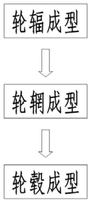
[0045] The automobile wheel processing technology in the present embodiment is basically as figure 1 As shown, it specifically includes the following steps:

[0046] S1, spoke forming: spoke 15 (such as Figure 11 shown) is formed by low-temperature and low-pressure casting process. Specifically, the aluminum ingot is smelted, refined and degassed, and then formed by using a low-pressure casting mold at a temperature of 645-660 ° C. Then, solution heat treatment, aging heat treatment and lathe Composite port (this part is prior art, not repeating it here), obtains wheel spoke 15. Specifically, in this embodiment, the low-temperature and low-pressure casting method of the spoke 15 refers to a casting casting method disclosed in the Chinese invention patent application (CN110560664A).

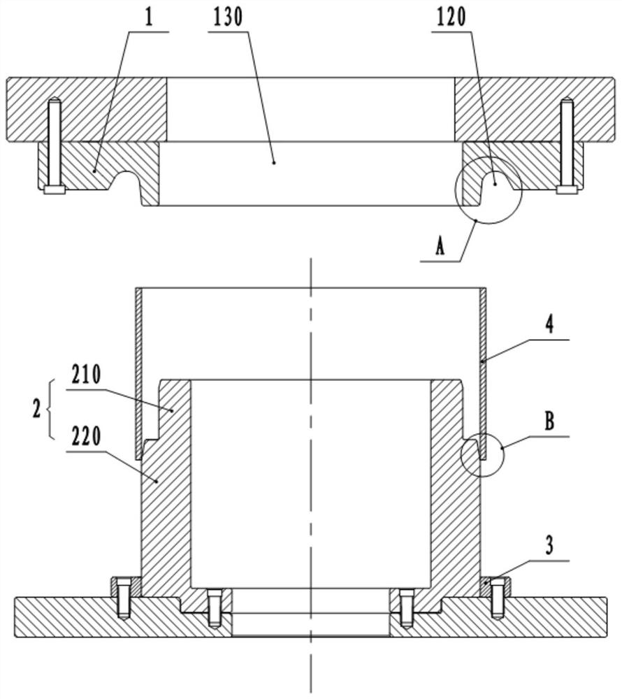
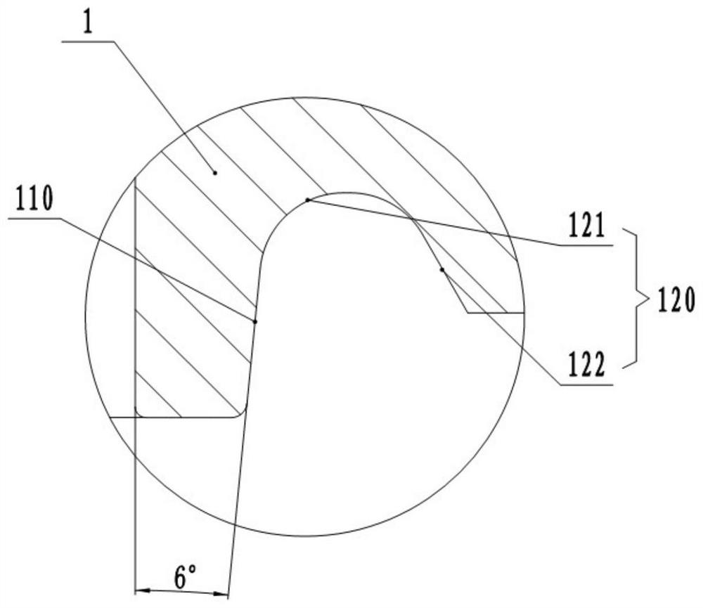
[0047] S2. Forming the rim: the aluminum plate (O-state 6061 aluminum plate, copper content 0.2-0.3%) is cut, rolled into a circle, flattened, and then welded into a cylinder 4 . In the above ...

Embodiment 2

[0070] The difference between this embodiment and Embodiment 1 is that: Figure 12 with Figure 13 As shown, in this embodiment, in step S2, in the flanging mold used in the flanging forming step, the lower end of the upper mold 1 is provided with a hanging lug 16, and the hanging lug 16 includes a vertical portion 161 and a horizontal portion 162, The vertical part 161 is connected and fixed with the upper mold 1 by bolts, and the horizontal part 162 can be offset against the curling of the cylinder 4 after flanging.

[0071] In actual use, when the cylinder 4 is flanged at the top, the crimp formed after the top flanging of the cylinder 4 is located above the horizontal portion 162 of the hanging lug 16 . When the upper mold 1 moves upwards and resets under the drive of the driving part, the curling at the top of the cylinder 4 will be hooked on the horizontal part 162 of the hanging ear 16, thereby lifting the cylinder 4 upwards, so that the cylinder 4 is disengaged. The ...

Embodiment 3

[0072] Embodiment 3: The difference between this embodiment and Embodiment 1 is that the preload of the elastic member 10 is 300N.


PUM

PropertyMeasurementUnit
diameteraaaaaaaaaa
diameteraaaaaaaaaa

Abstract

The invention relates to the field of hub machining, and discloses an automobile hub machining process. The process comprises the following steps: (1) spoke forming; (2) rim forming, specifically, a rim is manufactured by conducting flanging forming and spinning forming on a cylinder, and in the spinning forming step, a spinning cutter assembly is used for conducting spinning on the cylinder subjected to flanging forming; and the spinning cutter assembly comprises a first spinning cutter for primarily spinning the outer wall of the cylinder, a second spinning cutter for spinning the end part of the cylinder and a third spinning cutter for finely spinning the outer wall of the cylinder; and (3) hub forming, specifically, a spoke obtained in the step (1) and the rim obtained in the step (2) are composited to obtain a composite area, the composite area is welded, and a hub is obtained. In the process, the spoke and the rim are separately molded and manufactured, so that the modular line production of hub production is realized, the yield of the hub is greatly improved, the lightweight design of the hub is realized, and the driving performance of an automobile is improved. In addition, the problems that in the rim forming process, die attaching is not achieved, and the rim wall is spun too thin can be solved.

Description

technical field [0001] The invention relates to the field of wheel hub processing, in particular to an automobile wheel hub processing technology. Background technique [0002] The wheel hub is a barrel-shaped metal part whose center is mounted on the shaft, and is also called a rim, a steel ring, a wheel, and a tire bell. There are many kinds of hubs according to diameter, width, molding method and material. At present, the traditional wheel hub manufacturing methods are mostly one-piece molding, melting aluminum ingots, and forming spokes and rim assemblies with low-pressure casting. However, the wheel hub produced by this method has a large mass and high inertia, and the deformation is also large when rotating at high speed, which affects the driving performance of the car and increases fuel consumption. [0003] In view of the above problems, the inventor manufactured the spokes and the rim separately. However, during the rim forming process, it was found that when the...

Claims


Application Information

Patent Timeline
Patent Type & Authority Applications(China)
IPC IPC(8): B23P15/00B60B21/00B60B27/00
CPCB23P15/00B60B27/00B60B21/00Y02T10/86
Inventor 张福建王禄勇
Owner 重庆市超群工业股份有限公司
Learn More