
Pyrolysis furnace and pyrolysis system for treating dioxin in waste incineration fly ash

A technology for waste incineration fly ash and pyrolysis furnace, which is applied in the field of pyrolysis furnace and pyrolysis system, can solve the problem of low removal rate of fly ash dioxin, difficulty in realizing fly ash dioxin anaerobic atmosphere conditions, fly ash Heat agglomeration, poor discharge and other problems, to ensure uniform temperature, improve temperature field distribution, avoid heat agglomeration effect

Inactive Publication Date: 2021-07-13
浙江京兰环保科技有限公司
View PDF9 Cites 5 Cited by
  • Summary
  • Abstract
  • Description
  • Claims
  • Application Information

AI Technical Summary

Problems solved by technology

However, it fails to solve the problems of agglomeration and poor discharge caused by uneven heating of fly ash, and it is difficult to realize the anaerobic atmosphere conditions during the thermal decomposition of fly ash dioxins, and the removal rate of fly ash dioxins not tall

Method used


Image

  • Pyrolysis furnace and pyrolysis system for treating dioxin in waste incineration fly ash
  • Pyrolysis furnace and pyrolysis system for treating dioxin in waste incineration fly ash
  • Pyrolysis furnace and pyrolysis system for treating dioxin in waste incineration fly ash

Examples


Embodiment 1

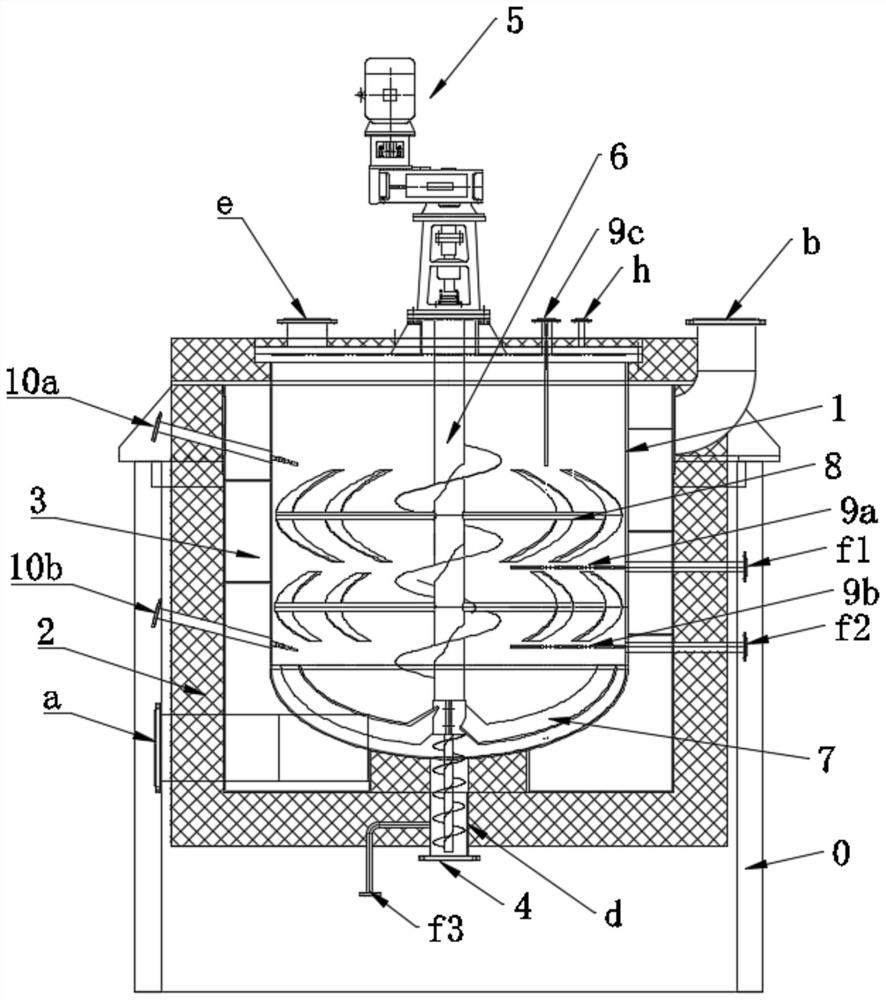
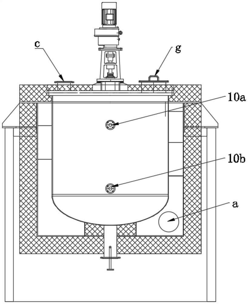
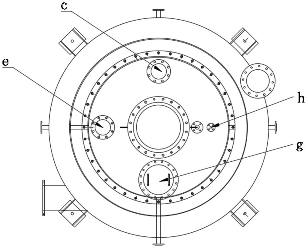
[0032] Such as Figure 1-3 As shown, the pyrolysis furnace for processing waste incineration fly ash dioxin in this embodiment is set up on the support 0. Specifically, the pyrolysis furnace includes a furnace hearth 1, which is a vertical structure; the outer sealing cover of the furnace hearth 1 is provided with a thermal insulation shell 2, and a sealed flue 3 is formed between the furnace hearth and the heat insulation shell, and the flue 3 It is a spiral structure extending along the axial direction of the furnace (that is, the height direction), thereby increasing the residence time of hot flue gas outside the furnace and the heat transfer area, and improving the utilization rate of heat energy.

[0033] The heat insulation shell 2 of this embodiment has a hot air inlet a and a hot air outlet b, both of which are connected to the flue 3 and are respectively located at both ends of the flue; that is, the hot air inlet a is located at the bottom of the flue , the hot air ...

Embodiment 2

[0056] The difference between the pyrolysis furnace of the present embodiment and embodiment 1 is:

[0057] A thermocouple temperature measurement module can also be added before the hot air inlet to ensure that the fly ash inside the furnace does not agglomerate and block by controlling the temperature of the hot flue gas.

[0058] Other structures can refer to Embodiment 1.

[0059] In addition, the pyrolysis system of this embodiment adopts the pyrolysis furnace of this embodiment, and other structures can refer to Embodiment 1.

Embodiment 3

[0061] The difference between the pyrolysis furnace of the present embodiment and embodiment 1 is:

[0062] The number of thermocouples is not limited to three in embodiment 1, and can also be one, two, four, five, etc., which can be set according to actual needs;

[0063] The quantity of material level meter is not limited to the two of embodiment 1, can also be one, three, four, five etc., specifically can be set according to actual demand;

[0064] The number of inert gas inlets is not limited to three in Embodiment 1, and can also be one, two, four, five, etc., which can be set according to actual needs;

[0065] Other structures can refer to Embodiment 1.

[0066] In addition, the pyrolysis system of this embodiment adopts the pyrolysis furnace of this embodiment, and other structures can refer to Embodiment 1.


PUM


Abstract

The invention relates to a pyrolysis furnace and a pyrolysis system for treating dioxin in waste incineration fly ash. The pyrolysis furnace comprises a hearth, the hearth is covered with a heat insulation shell in a sealing manner, a sealed flue is formed between the hearth and the heat insulation shell, and the flue is of a spiral structure extending in the axial direction of the hearth; the heat insulation shell is provided with a hot air inlet and a hot air outlet which are both communicated with the flue and located at the two ends of the flue respectively; the heat insulation shell is provided with a feeding hole and a discharging hole which are respectively used for feeding and discharging, and the feeding hole and the discharging hole are respectively communicated with the hearth; the discharging port is provided with a discharging throat pipe which is provided with a switch valve; and the heat insulation shell is provided with an exhaust port and an inert gas inlet which are communicated with the hearth. By means of the method, the dioxin in the waste incineration fly ash can be stably reduced to 50 ngTEQ / kg or below after being treated, and the problem that fly ash chlorine salt is heated and agglomerated can be avoided.

Description

technical field [0001] The invention belongs to the technical field of harmless treatment of garbage fly ash, and in particular relates to a pyrolysis furnace and a pyrolysis system for treating dioxins in garbage incineration fly ash. Background technique [0002] With the continuous advancement of urbanization, many large and medium-sized cities are troubled by "garbage siege". Waste incineration technology has become an effective method for urban waste reduction and has been widely used. But the fly ash after garbage incineration will cause environmental pollution. Fly ash refers to the residue collected by the flue gas purification system when the waste incineration power plant generates electricity. The total amount is about 3-5% of the domestic waste treatment volume. Strong alkaline, its high content of soluble salts promotes the dissolution of heavy metals in the environment, and also contains a certain concentration of organic pollutants such as chlorobenzene seri...

Claims


Application Information

Patent Timeline
Patent Type & Authority Applications(China)
IPC IPC(8): B09B3/00B09B5/00
CPCB09B5/00B09B2101/30B09B3/40
Inventor 赵星磊李斌朱富强王鹏宇吴侬利陆懿铭赵伟光
Owner 浙江京兰环保科技有限公司
Learn More