
Carbon-plastic composite bipolar plate for fuel cell as well as preparation and application thereof

A bipolar plate, carbon plastic technology, applied in the direction of fuel cells, circuits, electrical components, etc., can solve the problems of reduced bipolar plate cost, low production efficiency, high production cost, and achieve good product quality, low cost, and resin reduction. The effect of content

Pending Publication Date: 2021-06-18
DALIAN INST OF CHEM PHYSICS CHINESE ACAD OF SCI
View PDF10 Cites 3 Cited by
  • Summary
  • Abstract
  • Description
  • Claims
  • Application Information

AI Technical Summary

Problems solved by technology

However, the bipolar plate prepared by this process requires a curing time of up to 1 day, and the production efficiency is low, which is not conducive to the reduction of the cost of the bipolar plate, and the preparation cost is high

Method used


Image

  • Carbon-plastic composite bipolar plate for fuel cell as well as preparation and application thereof
  • Carbon-plastic composite bipolar plate for fuel cell as well as preparation and application thereof
  • Carbon-plastic composite bipolar plate for fuel cell as well as preparation and application thereof

Examples


Embodiment 1

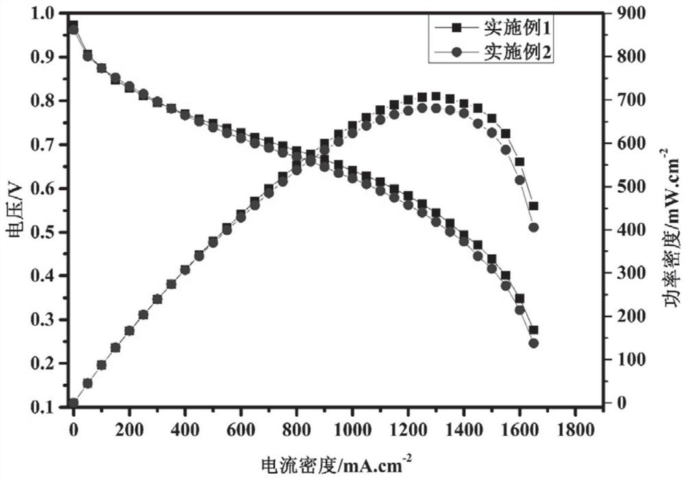
[0031] Weigh respectively PPS resin (molecular weight is 100,000) 1.0kg, PVDF resin (molecular weight is 300,000) 0.8kg, SEBS resin (styrene content 15%, melt index is 6g / 10min under 200 ℃) 0.2kg, natural flake graphite Powder (purity 99.0%, 400 mesh) 8.5kg, carbon fiber (diameter is 5 μm, aspect ratio is 20) 0.4kg, join in the ball mill, ball milling temperature is room temperature 25 ℃, ball milling speed is 50r / min, ball milling time 20min. Then the uniformly mixed material was transferred to a mold with a flow field, the pre-compression pressure was 60MPa, the molding temperature was 320°C, the molding pressure was 120MPa, and the molding time was 20min. Finally, the temperature of the mold was lowered to room temperature 25°C by circulating water cooling, and the carbon / polymer composite bipolar plate was obtained by releasing the pressure and demoulding. The operating conditions of the single cell are: the platinum loading of the cathode and anode is 0.4 / 0.2mg cm -2 , t...

Embodiment 2

[0033] Take by weighing PPS resin (molecular weight is 100,000) 1.5kg, PVDF resin (molecular weight is 300,000) 0.75kg, SEBS resin (styrene content 20%, melt index is 10g / 10min under 200 ℃) 0.2kg, natural flake graphite Powder (purity 99.0%, 400 mesh) 9.0kg, carbon fiber (diameter is 5 μm, aspect ratio is 20) 0.5kg, join in the ball mill, ball milling temperature is room temperature 25 ℃, ball milling speed is 80r / min, ball milling time 15min. Then the uniformly mixed material was transferred to a mold with a flow field, the pre-compression pressure was 80MPa, the molding temperature was 350°C, the molding pressure was 100MPa, and the molding time was 30min. Finally, the temperature of the mold was lowered to room temperature 25°C by circulating water cooling, and the carbon / polymer composite bipolar plate was obtained by releasing the pressure and demoulding.

[0034] The steps of applying the prepared composite bipolar plate to the fuel cell and the battery performance test ...


PUM

PropertyMeasurementUnit
melt flow indexaaaaaaaaaa
diameteraaaaaaaaaa
diameteraaaaaaaaaa

Abstract

The invention belongs to the field of fuel cells, and discloses a carbon-plastic composite bipolar plate for a fuel cell as well as preparation and application of the carbon-plastic composite bipolar plate. The composite bipolar plate is a carbon-plastic composite plate composed of polyphenylene sulfide, polyvinylidene fluoride, a hydrogenated ethylene-butylene-styrene triblock copolymer, a conductive filler and reinforced fibers. The selected filler is good in heat-conducting property, high in strength, good in chemical stability, very high in corrosion resistance and very high in electrical conductivity, and the mechanical property, the electrical conductivity and the heat-conducting property of the composite bipolar plate can be greatly improved. The body resistance and contact resistance of the bipolar plate can be greatly reduced, and the total battery performance is improved.

Description

technical field [0001] The invention belongs to the field of fuel cells, and in particular relates to a carbon-plastic composite bipolar plate for a fuel cell and its preparation and application. Background technique [0002] The increasingly severe energy problems and the environment force people to constantly seek new, cleaner and more efficient energy sources. Fuel cells are an energy conversion device that directly converts chemical energy into electrical energy. It has high energy conversion efficiency, high energy density, Many advantages, such as environmental friendliness, have been paid more and more attention by people. [0003] The current commercialized bipolar plates are mainly non-porous graphite plates and modified metal plates. The non-porous graphite plates are obtained by mixing graphite and graphitizable resin through complex graphitization process. The bipolar plate prepared by this method has low strength and requires a thickness of 3-5mm to maintain go...

Claims


Application Information

Patent Timeline
Patent Type & Authority Applications(China)
IPC IPC(8): H01M8/0213H01M8/0221H01M8/0226C08L81/02C08L27/16C08L53/02C08K3/04C08K7/06
CPCH01M8/0213H01M8/0221H01M8/0226C08L81/02C08K2201/003C08K2201/016C08K2201/001C08L2203/20C08L2205/03C08L27/16C08L53/025C08K3/04C08K7/06Y02E60/50
Inventor 邵志刚吕波何良王朋豪苟勇
Owner DALIAN INST OF CHEM PHYSICS CHINESE ACAD OF SCI
Learn More