
Anti-emulsification liquid distribution sleeve and anti-emulsification centrifugal extractor

A centrifugal extractor and anti-emulsification technology, applied in liquid solution solvent extraction, solvent extraction, separation methods, etc., can solve the problems of low mass transfer efficiency, single mixing method, high stagnation rate of ring gap, etc., to improve mass transfer efficiency , reduce stagnation rate, uniform particle size effect

Active Publication Date: 2021-06-15
XIAN MODERN CHEM RES INST
View PDF10 Cites 0 Cited by
  • Summary
  • Abstract
  • Description
  • Claims
  • Application Information

AI Technical Summary

Problems solved by technology

However, the above-mentioned equipment has problems such as single mixing method, serious emulsification of two-phase mixing, low mass transfer efficiency, and high liquid stagnation rate in the annulus, and is not suitable for current applications such as extraction of traditional Chinese medicine, treatment of high-concentration phenol-containing wastewater, and removal of metal cations by high-viscosity copolymerization compounds. The application of two-phase system rapid separation such as centrifugal extraction of organic azide compounds

Method used


Image

  • Anti-emulsification liquid distribution sleeve and anti-emulsification centrifugal extractor
  • Anti-emulsification liquid distribution sleeve and anti-emulsification centrifugal extractor
  • Anti-emulsification liquid distribution sleeve and anti-emulsification centrifugal extractor

Examples


Embodiment 1

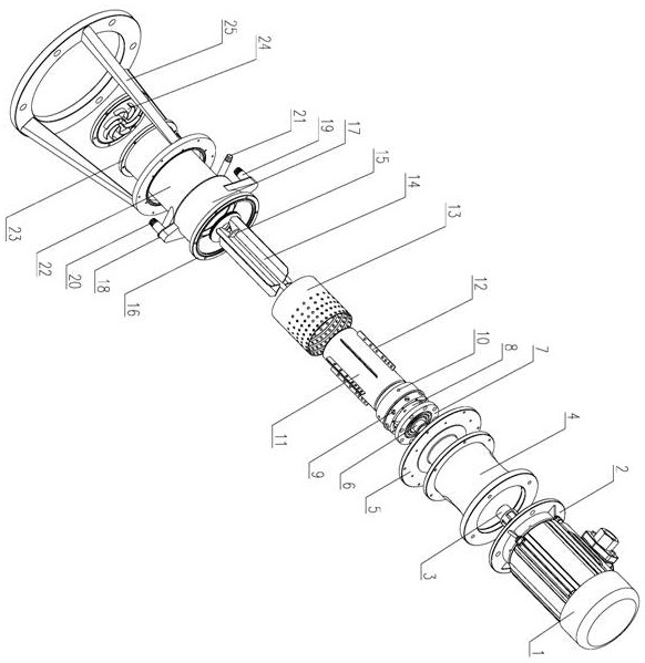
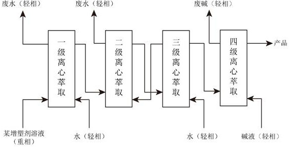
[0050] Such as figure 1 and figure 2 As shown, this embodiment provides a centrifugal extractor in the preparation process of liquid energetic plasticizer nitroazide compound, in which the liquid distribution sleeve of the above design is used.

[0051] Motor 1 is an explosion-proof three-phase asynchronous motor.

[0052] The design of bottom flange 24 adopts 8 vortex vanes as guide vanes, and the distance from the mixed liquid suction inlet of the rotating drum is 5mm.

[0053] In the rotating assembly, diversion holes are provided every 35 mm on the upper part of the outer wall 301 of the drum as the heavy phase outlet 9 and the light phase outlet 10; the interval between the heavy phase weir plate 8 and the light phase weir plate is 20 mm.

[0054] The anti-emulsion cloth liquid sleeve 13 is fixed on the bottom flange 24 by welding.

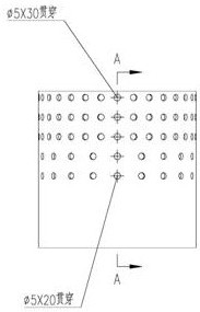
[0055] The inner diameter of the anti-emulsification liquid distribution sleeve 13 is 1 / 3 of the ring-to-ring ratio difference between t...

Embodiment 2

[0062] This embodiment provides a design of an anti-emulsification device for a centrifugal extractor in the aluminum ammonium sulfate solution for iron removal in the alumina preparation process, including a preferred centrifugal extractor and an annular liquid distribution device on the inner wall of the shell with an anti-emulsification function design plate. Compared with the centrifugal extractor that embodiment 1 provides, the difference is:

[0063] The motor 1 in the transmission part is a non-explosion-proof asynchronous three-phase motor, and the bottom flange 24 is designed to use 6 flat blades as guide vanes, and the distance between it and the mixed liquid suction inlet of the drum is 20 mm.

[0064] The anti-emulsification device is used in the process of extracting alumina from fly ash. Considering the cost of extraction agent dissolution loss and stripping performance effect, two or three of aluminum ammonium sulfate solution, phosphate esters and amine compoun...

Embodiment 3

[0070] This embodiment provides a design of an anti-emulsification device for a centrifugal extractor for the treatment of high-concentration phenol-containing wastewater, including a combined design of a preferred centrifugal extractor and a liquid distribution sleeve 13 with an anti-emulsification function + a liquid distribution structure. Compared with the centrifugal extractor that embodiment 1 provides, the difference is:

[0071] The motor 1 in the transmission part is a non-explosion-proof asynchronous motor, and the bottom flange 24 is designed to use 6 vortex blades as guide blades, and the distance between it and the mixed liquid suction inlet of the drum is 10 mm.

[0072] Considering the microemulsion extractant in the treatment process of high-concentration phenol-containing wastewater, it is often selected from a mixture of tributyl phosphate, medium oil and amine compounds or a trioctylamine solution or a complex extractant plus a mixture of multiple modifiers. ...


PUM


Abstract

The invention provides an anti-emulsification liquid distribution sleeve and an anti-emulsification centrifugal extractor. The anti-emulsification liquid distribution sleeve comprises a cylinder with two open ends, the cylinder is used for being coaxially installed between an outer shell and a rotary drum of the centrifugal extractor and fixed relative to the outer shell, and a plurality of layers of first liquid distribution holes are formed in the annular unfolding surface of the cylinder. The anti-emulsification liquid distribution sleeve is coaxially arranged between a rotary drum and an outer shell of the anti-emulsification centrifugal extractor; a plurality of layers of annular liquid distribution plates perpendicular to the inner wall of the outer shell are arranged in the circumferential direction of the inner wall of the outer shell; second liquid distribution holes are evenly distributed in each annular liquid distribution plate; a plurality of axial liquid distribution baffles are arranged on the outer wall of the rotary drum in a circumferential direction at equal intervals; and a plurality of third liquid distribution holes are formed in the liquid distribution baffles. After three optimized structural designs including the anti-emulsification liquid distribution sleeve, the annular liquid distribution plates and the axial liquid distribution baffles are independently applied, the mass transfer efficiency of an annular space mixing area can be effectively improved by 25-40%, a liquid retention rate is reduced by 50% or more, and the average particle size range of liquid drops in the annular space of the centrifugal extractor after optimization is controlled to be 40-50 microns.

Description

technical field [0001] The invention belongs to the technical field of centrifugal extraction, and in particular relates to an anti-emulsification cloth liquid sleeve and an anti-emulsification centrifugal extraction machine. Background technique [0002] Emulsification is the effect of one liquid uniformly dispersed in another immiscible liquid in the form of tiny droplets. Emulsification is a liquid-liquid interface phenomenon. Two immiscible liquids, such as oil and water, are divided into two layers in a container. The oil with low density is in the upper layer, and the water with high density is in the lower layer. If appropriate surfactant is added and the oil is dispersed in water under strong stirring, an emulsion is formed. This process is called emulsification. [0003] Centrifugal extractor realizes liquid-liquid two-phase contact mass transfer and phase separation with the help of centrifugal force field. It has the characteristics of compact structure, large pr...

Claims


Application Information

Patent Timeline
Patent Type & Authority Applications(China)
IPC IPC(8): B01D11/04
CPCB01D11/0476
Inventor 汪营磊白志山高福磊董霄李亚南陈斌刘卫孝闫峥峰
Owner XIAN MODERN CHEM RES INST
Learn More