
Heat sink structure design method based on contour extraction

A technology of contour extraction and structural design, applied in computer-aided design, calculation, instrument, etc., can solve the problems of unsatisfactory heat dissipation performance of MCFHS, poor flow and cooling capacity in wake area, pressure loss, etc., and achieve uniform temperature distribution on the bottom surface, Good convection heat transfer performance and small overall thermal resistance

Inactive Publication Date: 2021-06-11
WUHAN UNIV
View PDF2 Cites 0 Cited by
  • Summary
  • Abstract
  • Description
  • Claims
  • Application Information

AI Technical Summary

Problems solved by technology

[0004] However, through the analysis of the heat transfer characteristics and flow characteristics of the existing MCFHS, it is found that the heat flux in the wake area downstream of the circular pin fin is low, which indicates that compared with the stronger flow heat transfer efficiency outside the wake area, The flow and cooling capacity of the wake area is poor, coupled with the pressure loss caused by the eddy current caused by flow separation, the heat dissipation performance of MCFHS is difficult to meet the heat dissipation problem of MEMS with higher energy density

Method used


Image

  • Heat sink structure design method based on contour extraction
  • Heat sink structure design method based on contour extraction
  • Heat sink structure design method based on contour extraction

Examples


Embodiment Construction

[0032] The following will clearly and completely describe the technical solutions and specific implementation methods of the present invention with reference to the accompanying drawings in the present invention.

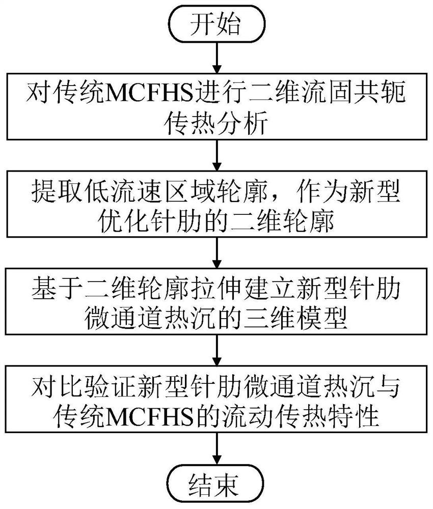
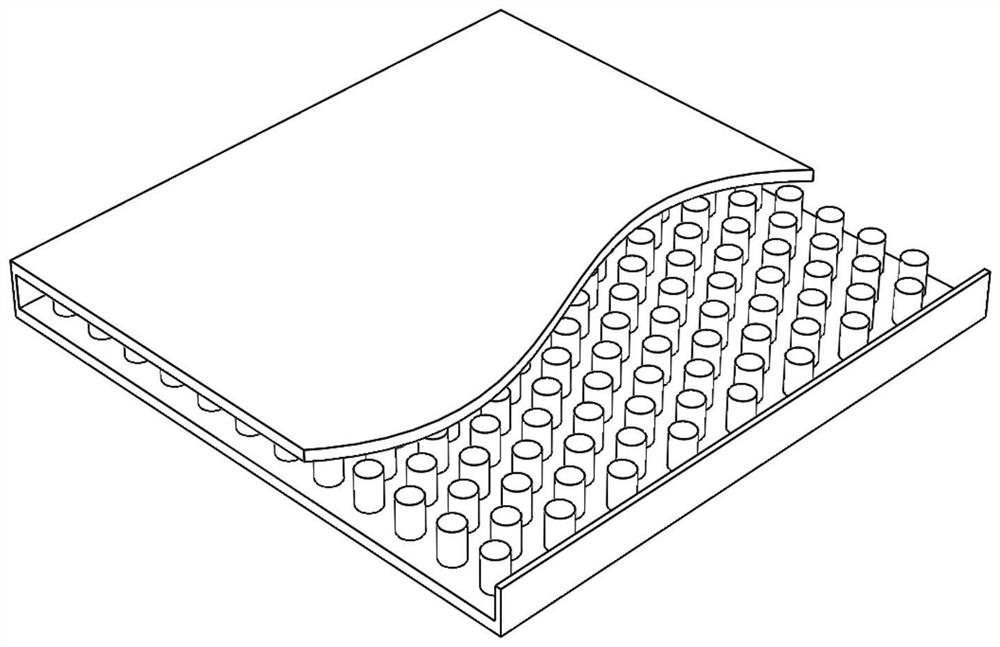
[0033] Such as figure 2 Shown is the optimization object in this example, that is, the traditional MCFHS, its overall size is 25mm*25mm*2.5mm, the solid substrate material used is copper, and the cooling liquid is water. According to the heat sink structure design method based on contour extraction designed in the present invention, its optimal design process includes the following steps:

[0034] S1: Through the fluid-solid conjugate two-dimensional heat transfer model pair figure 2 Analysis of flow characteristics and heat transfer characteristics in traditional MCFHS;

[0035] S2: Extract the contour of the low-velocity area around the cylindrical needle fin as the 2D contour of the new needle fin;

[0036] S3: Based on the obtained 2D profile of the new pin...


PUM


Abstract

The invention relates to a heat sink structure design method based on contour extraction. The method comprises the following steps: firstly, establishing a two-dimensional heat transfer model of a traditional cylindrical micro-pin-fin heat sink, carrying out numerical calculation on the model, and analyzing flow characteristics and heat transfer characteristics; extracting a two-dimensional contour of a low-flow-speed area in the speed cloud picture, and designing a novel three-dimensional model of the micro-pin-fin heat sink based on the two-dimensional contour; and then carrying out numerical calculation and comparative analysis on the designed novel micro-pin-fin heat sink three-dimensional model and the traditional MCFHS three-dimensional model under the same condition. The novel micro pin fin designed according to the design method has a larger cross sectional area and a streamline shape, obtains a larger fluid-solid contact heat exchange area, improves heat transfer efficiency, eliminates eddy current in a circular pin fin wake flow area in a traditional MCFHS, reduces pressure loss, and is better in flowing property and higher in heat transfer efficiency. The overall cooling performance of the heat sink is improved.

Description

technical field [0001] The invention belongs to the technical field of thermal energy engineering, and in particular relates to a structural design optimization method suitable for microchannel heat sinks of high-power electronic integrated devices. Background technique [0002] With the rapid development of Micro Electro-Mechanical System (MEMS) toward high integration and miniaturization, the energy density in MEMS continues to increase, accompanied by the continuous increase of chip heat inside the system, which makes its The heat dissipation performance requirements of thermal management devices are becoming more and more stringent. In 1981, the introduction of Microchannel heat sink (MCHS) provided an efficient cooling technology for high-power electronic equipment. In the follow-up research on MCHS, researchers obtained better cooling performance by optimizing its size parameters, inner wall shape, channel structure, etc. [0003] Compared with traditional MCHS, Micr...

Claims


Application Information

Patent Timeline
IPC IPC(8): G06F30/398G06F119/08G06F119/14
CPCG06F30/398G06F2119/08G06F2119/14
Inventor 李辉黄贻苍申胜男赵亮
Owner WUHAN UNIV
Learn More