
Heat exchanger and gas equipment

A heat exchanger and equipment technology, applied in lighting and heating equipment, fluid heaters, etc., can solve the problems of prone to condensation, freeze cracking of coils, high cost, etc., to avoid external heat radiation and reduce the cost of coils. The effect of using and simplifying the production process

Pending Publication Date: 2021-06-11
WUHU MIDEA KITCHEN & BATH APPLIANCES MFG CO LTD +1
View PDF0 Cites 0 Cited by
  • Summary
  • Abstract
  • Description
  • Claims
  • Application Information

AI Technical Summary

Problems solved by technology

[0003] In order to cool down the outer surface of the box and avoid damage to components caused by heat radiation to the outside, there are two schemes currently adopted: one is that a coil is usually installed around the outside of the box, and the surface temperature of the box is reduced through the coil. The process is complicated, the cost is high, and the coil is prone to condensed water. In the harsh environment of use, the coil is also prone to problems such as frost cracking and corrosion perforation.
; The second is to install heat insulation cotton on the inside of the box, but the thickness and tightness of the heat insulation cotton will affect the heat insulation effect, and the price is relatively high

Method used


Image

  • Heat exchanger and gas equipment
  • Heat exchanger and gas equipment
  • Heat exchanger and gas equipment

Examples


Embodiment Construction

[0038] Embodiments of the present invention are described in detail below, and examples of the embodiments are shown in the drawings, wherein the same or similar reference numerals denote the same or similar elements or elements having the same or similar functions throughout. The embodiments described below by referring to the figures are exemplary and are intended to explain the present invention and should not be construed as limiting the present invention.

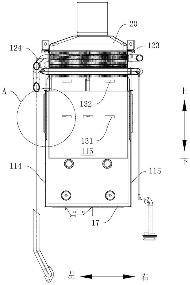
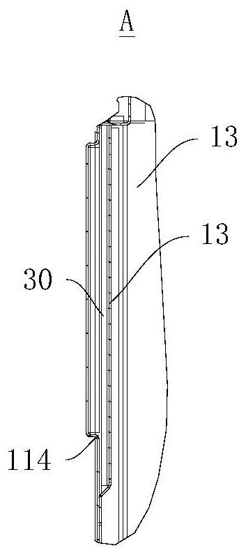
[0039] Now refer to Figure 1-Figure 8 , describes the heat exchanger 10 according to the embodiment of the present invention, the heat exchanger 10 includes: a box body 11 , a clamping plate 13 and a heat exchange assembly 12 .

[0040] Specifically, such as figure 2 combine image 3 ,Such as Figure 4 combine Figure 5 As shown, the box body 11 defines a combustion chamber 115 , and the heat exchange assembly 12 is built in the box body 11 and located above the combustion chamber 115 . It can be understood that...


PUM


Abstract

The invention discloses a heat exchanger and gas equipment. The heat exchanger comprises a box body, a heat exchange assembly and clamping plates, wherein a combustion chamber is formed in the box body, the heat exchange assembly is arranged in the box body and located above the combustion chamber, the clamping plates are arranged on the inner side of the box body in a separated mode, an air cooling channel is formed between the box body and the clamping plates, the air cooling channel is arranged on the periphery of the combustion chamber in a surrounding mode, and at least one part of the air cooling channel is located on the outer side of the heat exchange assembly. According to the heat exchanger, the heat exchange assembly is arranged on the box body, the clamping plates are arranged in the box body, and therefore the air cooling channel is formed in the periphery of the combustion chamber and the periphery of the heat exchange assembly, the heat in the box body is effectively prevented from being radiated outwards, then parts of the gas equipment are prevented from being damaged by the high temperature, use of coil pipes is reduced, and the production technology of the heat exchanger is simplified.

Description

technical field [0001] The invention relates to the technical field of water heaters, and more specifically, to a heat exchanger and gas equipment. Background technique [0002] The heat exchanger of a traditional gas water heater usually includes: a box body and a heat exchange component. The heat exchange component is mainly composed of fins and heat exchange tubes passing through the fins. The box body is usually made of oxygen-free copper. [0003] In order to cool down the outer surface of the box and avoid damage to components caused by heat radiation to the outside, there are two schemes currently adopted: one is that a coil is usually installed around the outside of the box, and the surface temperature of the box is reduced through the coil. The process is complicated, the cost is high, and the coil is prone to condensed water. In the harsh environment of use, the coil is also prone to problems such as frost cracking and corrosion perforation. ; The second is to ins...

Claims


Application Information

Patent Timeline
Patent Type & Authority Applications(China)
IPC IPC(8): F24H9/18F24H9/00
CPCF24H9/0005F24H9/18F24H9/1836
Inventor 杨万沔杜小文李龙李晓强梁国荣
Owner WUHU MIDEA KITCHEN & BATH APPLIANCES MFG CO LTD
Learn More