
A frequency stable low dielectric microwave dielectric ceramic material and its preparation method

A technology of microwave dielectric ceramics and ceramic materials, applied in the field of material science, can solve the problems of easily limited material application, difficult frequency temperature coefficient, poor frequency stability of related devices, etc., to achieve good process operability and reproducibility, and optimized frequency. The effect of good temperature coefficient and microwave dielectric properties

Active Publication Date: 2022-02-22
JIAXING GLEAD ELECTRONICS CO LTD
View PDF11 Cites 0 Cited by
  • Summary
  • Abstract
  • Description
  • Claims
  • Application Information

AI Technical Summary

Problems solved by technology

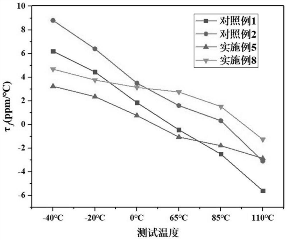
However, in practical applications, due to the simple perovskite structure of CaTiO 3 , SrTiO 3 or Ca 1-x Sr x TiO 3 The linearity of the temperature coefficient of the corresponding product is poor, and the frequency temperature coefficient of the corresponding product is difficult to satisfy τ in the whole temperature range (such as -40 ° C ~ 110 ° C) at the same time f The requirement of ≤±5ppm / ℃, the frequency stability of related devices is poor, which limits its use in mobile base stations
[0005] On the other hand, due to the sintering process of Mg 2+ Si 4+ There is a big difference in the diffusion rate, and it is very easy to form the second phase MgSiO 3 or incompletely reacted SiO 2
Since MgSiO 3 The loss is much greater than that of Mg 2 SiO 4 phase, which seriously deteriorates the Mg 2 SiO 4 Dielectric Properties of Ceramics
while excess SiO 2 It is easy to form a liquid phase during the sintering process, resulting in abnormal grain growth, which will also deteriorate the dielectric properties and mechanical strength of the material.
Patent CN101429015 discloses a method for adjusting the ratio of Mg / Si to eliminate the second phase, but the sintering temperature is relatively high and τ f Adjust to near 0, the material application is easily limited

Method used


Image

  • A frequency stable low dielectric microwave dielectric ceramic material and its preparation method
  • A frequency stable low dielectric microwave dielectric ceramic material and its preparation method

Examples


Embodiment 1

[0029] 1) Synthesis of main phase ceramic material A:

[0030] According to the chemical formula Mg 2.00 co 0.10 SiO 4.10 Measuring ratio weighing raw materials MgO, SiO 2 and CoO, add deionized water according to the ratio of mixture to deionized water 1:3, mix and grind for 20 hours, then dry in an oven at 120°C, grind with a quartz mortar and pass through a 40-mesh sieve, and then put the powder into alumina The crucible was calcined at 1250°C for 3 hours to obtain the main phase calcined powder A.

[0031] 2) Synthesis of auxiliary phase ceramic material B:

[0032] According to the chemical composition 0.99CaO·0.11SrO-0.06La 2 o 3 0.05Al 2 o 3 -1.00TiO 2 Weigh raw material CaCO 3 , SrCO 3 , La 2 o 3 、Al 2 o 3 and TiO 2 Mix, add deionized water according to the ratio of mixture and deionized water 1:2, mix and grind for 16 hours, then dry in an oven at 120°C, grind with a quartz mortar and pass through a 40-mesh sieve, and then put the powder into alumina ...

Embodiment 2

[0035] 1) Synthesis of main phase ceramic material A:

[0036] According to the chemical formula Mg 2.02 Zn 0.05 SiO 4.07 Measuring ratio weighing raw materials MgO, SiO 2 and ZnO, add deionized water according to the ratio of mixture to deionized water 1:3, mix and grind for 16 hours, then dry in an oven at 120°C, grind with a quartz mortar and pass through a 40-mesh sieve, and then put the powder into alumina The crucible was calcined at 1200°C for 3 hours to obtain the main phase calcined powder A.

[0037] 2) Synthesis of auxiliary phase ceramic material B:

[0038] According to the chemical composition 1.05CaO·0.12SrO-0.08Nd 2 o 3 0.06Al 2 o 3 -1.05TiO 2 Weigh raw material CaCO 3 , SrCO 3 、Nd 2 o 3 、Al 2 o 3 and TiO 2 For mixing, add deionized water according to the ratio of mixture and deionized water 1:2, mix and grind for 20 hours, then dry in an oven at 120°C, grind with a quartz mortar and pass through a 40-mesh sieve, and then put the powder into alu...

Embodiment 3

[0041] 1) Synthesis of main phase ceramic material A:

[0042] According to the chemical formula Mg 1.95 co 0.10 SiO 4.05 Measuring ratio weighing raw materials MgO, SiO 2 and CoO, add deionized water according to the ratio of mixture to deionized water 1:3, mix and grind for 20 hours, then dry in an oven at 120°C, grind with a quartz mortar and pass through a 40-mesh sieve, and then put the powder into alumina The crucible was calcined at 1150°C for 4 hours to obtain the main phase calcined powder A.

[0043] 2) Synthesis of auxiliary phase ceramic material B:

[0044] According to the chemical composition 1.25CaO·0.20SrO-0.15La 2 o 3 0.12Al 2 o 3 -1.20TiO 2 Weigh raw material CaCO 3 , SrCO 3 , La 2 o 3 、Al 2 o 3 and TiO 2 Mix, add deionized water according to the ratio of mixture and deionized water 1:2, mix and grind for 16 hours, then dry in an oven at 120°C, grind with a quartz mortar and pass through a 40-mesh sieve, and then put the powder into alumina ...


PUM

PropertyMeasurementUnit
frequency temperature coefficientaaaaaaaaaa

Abstract

The invention relates to a frequency-stable low dielectric microwave dielectric ceramic material and a preparation method thereof. The material consists of a main phase ceramic material A with a mass percentage of 70% to 90%, a secondary phase ceramic material B with a mass percentage of 10% to 30% and 0-1.0% oxide sintering aid C composition. The main phase ceramic material A is Mg x Me y SiO 2+x+y , the B composition of the subphase ceramic material is aRO‑bRe 2 o 3 ‑cTiO 2 , R is at least one of Ca or Sr, Re 2 o 3 for Sm 2 o 3 、Nd 2 o 3 , Y 2 o 3 、Al 2 o 3 and La 2 o 3 At least two of them, the oxide sintering aid C is MnO 2 、WO 3 and CeO 2 at least one of the The dielectric constant of the microwave dielectric ceramic material prepared by the present invention is 9.5 to 13.6, and the frequency temperature coefficient τ f It is continuously adjustable from -16ppm / °C to 13ppm / °C, and has good frequency stability. It is suitable for the fields of new generation mobile communication and high frequency network communication.

Description

technical field [0001] The invention belongs to the technical field of material science, and in particular relates to a frequency-stable low-medium microwave dielectric ceramic material and a preparation method thereof. Background technique [0002] Microwave dielectric ceramics are functional ceramic materials used in microwave frequency circuits to achieve one or more functions. They play an important role in the application of modern communication technology. key material. With the new generation of mobile communication and high-frequency network communication, the requirements for low delay and reliability of signal transmission are getting higher and higher, and microwave dielectric ceramic materials with low dielectric constant and excellent temperature coefficient stability have received more and more attention. Typical applications, such as filters in 5G base stations, usually require that the frequency temperature coefficient of -40°C to 110°C be within ±5ppm / °C, s...

Claims


Application Information

Patent Timeline
Patent Type & Authority Patents(China)
IPC IPC(8): C04B35/20C04B35/64
CPCC04B35/20C04B35/64C04B2235/3208C04B2235/3284C04B2235/3224C04B2235/3225C04B2235/3227C04B2235/3217C04B2235/3267C04B2235/442C04B2235/3258C04B2235/3229C04B2235/3232C04B2235/96
Inventor 刘顺国童建喜刘强黄丹胥金华史雪斌
Owner JIAXING GLEAD ELECTRONICS CO LTD
Learn More