
Laser impact precise formation method and device

A technology of laser shock and precision forming, which is applied in laser welding equipment, welding/welding/cutting items, manufacturing tools, etc. It can solve the problems of easily damaged optical lenses, complex tooling and fixtures, and unstable data, so as to improve the utilization of laser energy rate effect

Inactive Publication Date: 2003-11-26
JIANGSU UNIV
View PDF1 Cites 6 Cited by
  • Summary
  • Abstract
  • Description
  • Claims
  • Application Information

AI Technical Summary

Problems solved by technology

Its disadvantages are as follows: (1) Since the bending is caused by the strain generated by the residual compressive stress, the amount of deformation is small; (2) The bending of a large area is controlled by the stress distribution generated by point-by-point hammering, which is very difficult in practical applications. Difficulty; (3) Before the laser shock, an energy absorbing layer must be applied on the surface to be struck, and then water should be used as a constraining layer on the coating
This separate processing method causes disadvantages such as low laser energy utilization rate, unstable data, and poor reliability, and also requires a post-processing process to remove the residual energy-absorbing layer.
When water is used as the constraining layer, an additional water supply system is required, and the tooling fixture becomes complicated, and the splash of water during the laser hammering process is difficult to control, and the optical lens is easy to be damaged. (4) The forming material and process are single, and only for metal material hammering Bending forming and shape correction of rods

Method used


Image

  • Laser impact precise formation method and device
  • Laser impact precise formation method and device
  • Laser impact precise formation method and device

Examples


Embodiment Construction

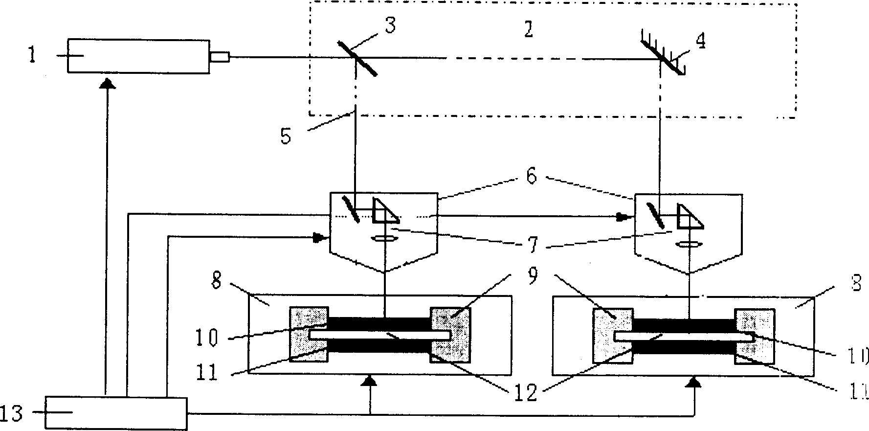
[0027] Combine below figure 1 , figure 2 Describe in detail the details and working conditions of the specific device proposed by the present invention.

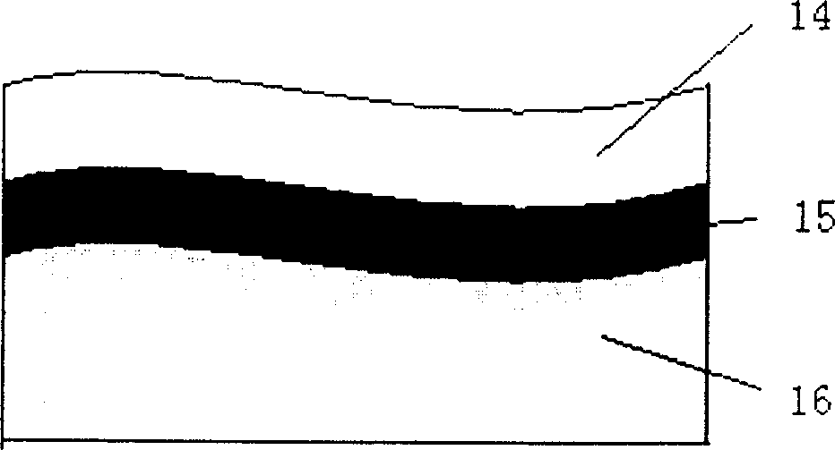
[0028] The laser shock precision forming device is composed of a control system 13, a laser device 1, a laser shock system, and a fixture system. The laser shock system consists of a light guide and light splitting system 2, a transmission mirror 3, a rotatable mirror 4, an optical lens group 5, a laser shock head 6, and a focusing lens group 7. The fixture system consists of a workbench 8, a fixture seat 9, an upper splint 10, a lower splint 11, a sample system 12, and a formed workpiece 16. figure 2 is the composition diagram of the flexible film, which includes the constraining part 14 constituting the flexible film and the energy absorbing part 15 constituting the flexible film, which are two components with different functions. The former acts to constrain the expansion of high-temperature plasma, and the latter ac...


PUM

PropertyMeasurementUnit
Pulse widthaaaaaaaaaa

Abstract

The present invention relates to machine building and is the laser shock method and equipment for precise formation especially suitable for metal sheet hard to form in conventional method. The equipment consists of laser, outer optical path system, fixture system and control system. The fixture system consists of working bench, fixture seat, upper fixing board, lower fixing board and sample assembly. The forming method is that the laser beam sent by the laser is transmitted via the outer optical path sstem to the surface of the workpiece in the fixture and the flexible film adhered to the surface of the workpiece is shocked to extrude the workpiece to produce plastic deformation fast. The present invention can form complicated shape with large plate and local fine shape by 3D shock, has high precision and good repeatability and is easy to use in automatic production.

Description

technical field [0001] The invention relates to the field of mechanical manufacturing, in particular to a laser shock precision forming method and device, which is suitable for the forming of thin metal plates, especially suitable for the forming of materials that are difficult or impossible to form by conventional methods, such as structural steel, titanium alloy, composite Materials, etc., can also be used for shape correction of rods. Background technique [0002] At present, there are many plastic forming methods for metal sheets at home and abroad, including stamping, explosive forming, shot peening and so on. The most common stamping forming to produce various sheet metal parts has the disadvantages of high mold cost and long production cycle, and can only be used for low-carbon thin plates (such as MB8, 10F, 20, 1Cr18Ni9Ti, etc.), aluminum alloys (such as LY12M, LY12C etc.), as well as copper and some brass, due to the influence of strain rate, the forming limit is l...

Claims


Application Information

Patent Timeline
IPC IPC(8): B21D26/06B23K26/00
CPCB23K2203/14B23K26/0069B23K2203/10B23K26/356B23K2103/10B23K2103/14
Inventor 张永康周明周建忠
Owner JIANGSU UNIV
Learn More