Scrap treatment device for metal material machining

A metal material and processing device technology, which is applied in the field of chip processing devices for metal material processing, can solve the problems of easy rusting of chips, unfavorable recycling, poor storage effect, etc.

Pending Publication Date: 2021-05-28
潘慧贤
View PDF12 Cites 2 Cited by
  • Summary
  • Abstract
  • Description
  • Claims
  • Application Information

AI Technical Summary

Problems solved by technology

[0002] Metal materials refer to metal elements or materials with metal properties mainly composed of metal elements, including pure metals, alloys, metal materials, intermetallic compounds and special metal materials, etc., usually divided into ferrous metals, non-ferrous metals and special materials Metal materials generally refer to pure metals or alloys in industrial applications. There are about 70 kinds of pure metals in nature, among which iron, copper, aluminum, tin, nickel, gold, silver, lead, zinc, etc. are common, and Alloys often refer to two or more metals or a combination of metals and non-metals, and have metallic properties. Common alloys such as steel alloys composed of iron and carbon, brass formed by copper and zinc, etc.; During the processing of metal materials, a lot of debris will be generated. Generally, the debris will be collected and stored for recycling. However, during the storage of debris, since the debris is not dried, the debris is prone to rust. The storage effect is not good, which is not conducive to subsequent recycling, and needs to be improved

Method used


Image

  • Scrap treatment device for metal material machining
  • Scrap treatment device for metal material machining
  • Scrap treatment device for metal material machining

Examples


Embodiment Construction

[0033] In order to make the object, technical solution and advantages of the present invention clearer, the present invention will be further described in detail below in combination with specific embodiments and with reference to the accompanying drawings. It should be understood that these descriptions are exemplary only, and are not intended to limit the scope of the present invention. Also, in the following description, descriptions of well-known structures and techniques are omitted to avoid unnecessarily obscuring the concept of the present invention.

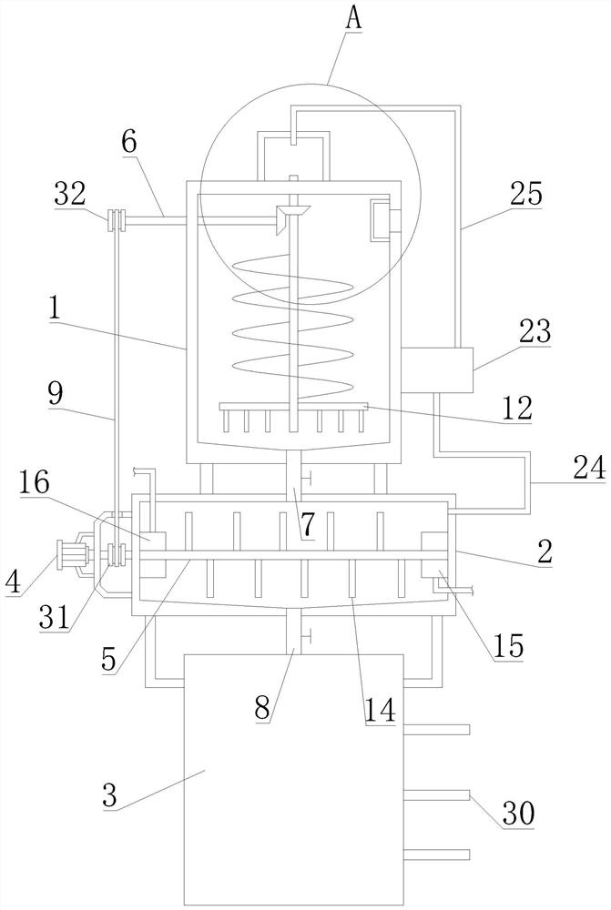
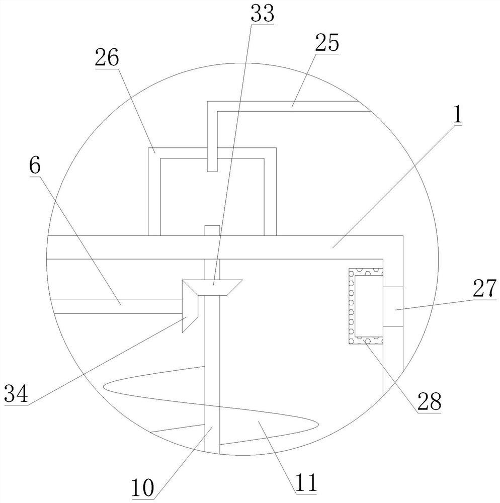
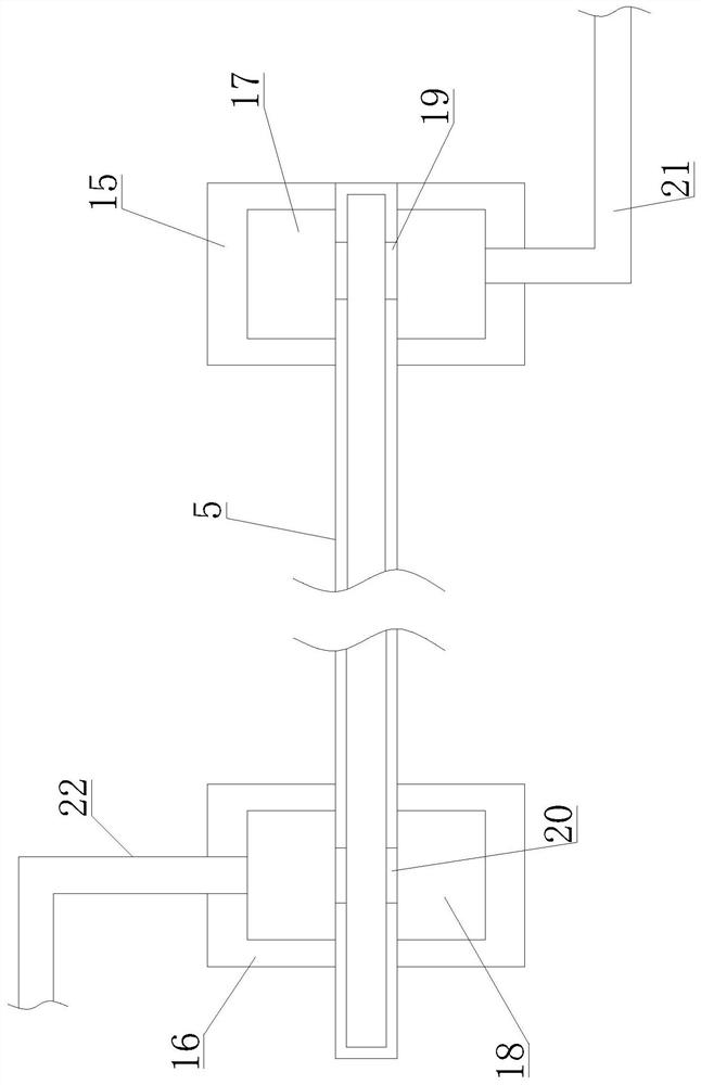
[0034] Such as Figure 1-5 As shown, a metal material processing chip treatment device proposed by the present invention includes a chip storage box 1, a drying box 2, a screening box 3, an infusion tube 5, a transmission rod 6, a first material delivery tube 7, a second Feeding pipe 8, transmission belt 9, air pipe 10, stirring blade 11, stirring pipe 14, liquid inlet pipe 21, liquid outlet pipe 22, exhaust pipe 24, air...


PUM


Abstract

A scrap treatment device for metal material machining comprises a scrap storage box and a drying box; a gas conveying pipe is rotationally connected with the scrap storage box, and the gas conveying pipe extends into a gas collecting box; stirring vanes are arranged on the gas conveying pipe, gas distributing pipes are arranged at the lower end of the gas conveying pipe, and gas outlet pipes are arranged at the bottoms of the gas distributing pipes; stirring pipes are arranged on a liquid conveying pipe and located in the drying box; the output end of the driving device is connected with the liquid conveying pipe; a transmission belt is in transmission connection with the liquid conveying pipe and a transmission rod, and the transmission rod is in transmission connection with the gas conveying pipe; a first connecting piece and a second connecting piece are arranged at the two ends of the interior of the drying box, and the liquid conveying pipe penetrates through the first connecting piece and the second connecting piece; and a gas exhaust pipe communicates with the drying box and a dehumidification device, and a gas return pipe communicates with the dehumidification device and the scrap storage box. According to the scrap treatment device for metal material machining, metal scraps can be dried to be prevented from being rusted, heat in hot wet gas generated in the drying process can be recycled, energy consumption is reduced, the functions are diversified, and the using effect is extremely good.

Description

technical field [0001] The invention relates to the technical field of metal processing, in particular to a chip processing device for processing metal materials. Background technique [0002] Metal materials refer to metal elements or materials with metal properties mainly composed of metal elements, including pure metals, alloys, metal materials, intermetallic compounds and special metal materials, etc., usually divided into ferrous metals, non-ferrous metals and special materials Metal materials generally refer to pure metals or alloys in industrial applications. There are about 70 kinds of pure metals in nature, among which iron, copper, aluminum, tin, nickel, gold, silver, lead, zinc, etc. are common, and Alloys often refer to two or more metals or a combination of metals and non-metals, and have metallic properties. Common alloys such as steel alloys composed of iron and carbon, brass formed by copper and zinc, etc.; During the processing of metal materials, a lot of ...

Claims


Application Information

Patent Timeline
Patent Type & Authority Applications(China)
IPC IPC(8): F26B11/16F26B21/00F26B25/04F26B25/02B07B1/04
CPCF26B11/16F26B21/001F26B25/04F26B25/02B07B1/04B07B2201/04
Inventor 潘慧贤
Owner 潘慧贤
Why Eureka
Try Eureka