Steam sampling pipe device for high-temperature and high-pressure steam pipeline of thermal power plant

A high-temperature, high-pressure, steam pipeline technology, applied in sampling devices, sampling, measuring devices, etc., can solve the problems of cracking, falling off, easy cracking, etc., and achieve the effect of improving reliability, high reliability, and high rigidity

Pending Publication Date: 2021-05-25
XIAN THERMAL POWER RES INST CO LTD
View PDF0 Cites 0 Cited by
  • Summary
  • Abstract
  • Description
  • Claims
  • Application Information

AI Technical Summary

Problems solved by technology

The shortcomings and deficiencies of the steam sampling tube are: the steam sampling tube 4 and the alloy steel socket 2 are austenite matrix and ferrite matrix respectively, which belong to dissimilar steel connections, and the chemical composition and thermal expansion coefficient between the two exist If there is a large difference, the fusion interface between the weld 3 and the socket 2 is easy to crack; in addition, during the operation of the unit, the steam sampling tube 4 is under the action of steam and the difference in thermal expansion coefficient, and the steam sampling tube 4 and nozzle 1 The interference fit between the openings turns into a clearance fit, which causes the steam sampling tube to vibrate under the action of steam, and then forms stress concentration at the root of the weld 3, causing the fusion interface between the weld 3 and the socket 2 to alternate Cracking and falling off under stress

Method used


Image

  • Steam sampling pipe device for high-temperature and high-pressure steam pipeline of thermal power plant
  • Steam sampling pipe device for high-temperature and high-pressure steam pipeline of thermal power plant
  • Steam sampling pipe device for high-temperature and high-pressure steam pipeline of thermal power plant

Examples


Embodiment example

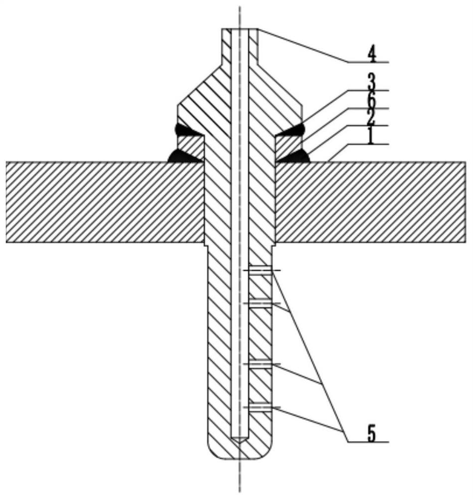
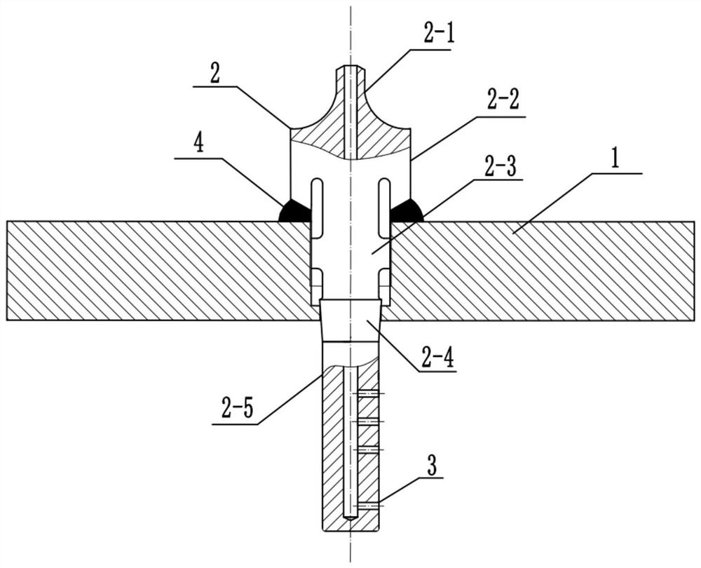
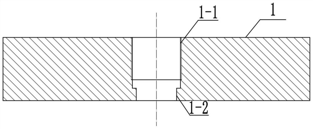
[0027] Implementation case: The original opening on the alloy steel pipe 1 is a full-diameter hole. Before installation, the upper part of the original opening of the alloy steel pipe 1 is reamed. The hole is coaxial with the inner wall of the upper nozzle of the alloy steel steam sampling pipe 2, and the diameter deviation of the upper nozzle of the newly reamed hole is less than 1 mm from the diameter of the upper nozzle of the alloy steel steam sampling pipe 2; The fine-toothed internal thread and the fine-toothed external thread of the small-diameter columnar body in the middle of the alloy steel steam sampling pipe 2 match the processing specifications of the internal thread on the inner wall of the reamed hole of the alloy steel pipe 1. The alloy steel steam sampling pipe 2 is screwed into the alloy steel pipe 1 through the outer thread of the small-diameter cylindrical outer thread in the middle part and the internal thread of the reaming inner wall of the alloy steel pi...


PUM

PropertyMeasurementUnit
diameteraaaaaaaaaa
thicknessaaaaaaaaaa

Abstract

The present invention discloses a steam sampling pipe device which is characterized in that a columnar hole and a circular boss which are communicated with each other are formed in the side wall of an alloy steel pipeline from outside to inside, and columnar hole internal threads are formed in the inner wall of the columnar hole; the alloy steel steam sampling pipe comprises a steam sampling pipe connecting pipe, an upper large-diameter cylindrical body which is positioned at the upper part of a cylindrical hole in the side wall of the alloy steel pipeline, is welded and connected by adopting a same steel fillet weld and is provided with a single V-shaped groove at the bottom, a middle small-diameter cylindrical body which is positioned in the cylindrical hole in the side wall of the alloy steel pipeline and is provided with an external thread, a cone-shaped body having the lower part being in contact with the circular boss of the alloy steel pipeline in an abutting manner, and a cylindrical body which is provided with a steam sampling hole and extends into the alloy steel pipeline; and the steam sampling pipe connecting pipe is connected with a steam sampling pipe system. The device is high in rigidity and not prone to vibration, and influences of weak interfaces of dissimilar steel weld joints and axial pressure of threads in the middle of the alloy steel steam sampling pipe on fillet weld joints of the alloy steel pipeline and the alloy steel steam sampling pipe are eliminated.

Description

technical field [0001] The invention relates to the technical field of steam sampling of high-temperature and high-pressure steam pipelines in thermal power plants, in particular to a steam sampling pipe device for high-temperature and high-pressure steam pipelines in thermal power plants. Background technique [0002] During the operation of thermal power plant units, in order to accurately reflect the quality of steam, prevent damage to equipment caused by insufficient steam purity, and ensure that the working fluid meets the design requirements, it is necessary to design and install several steam sampling devices on alloy steel pipes in thermal power plants. Real-time monitoring of the status of the working fluid to ensure the safe operation of the unit. [0003] figure 1 Shown is a schematic structural diagram of a conventional steam sampling tube. The steam sampling pipe 4 made of austenitic stainless steel goes deep into the interior of the pipe through the opening o...

Claims


Application Information

Patent Timeline
Patent Type & Authority Applications(China)
IPC IPC(8): G01N1/22
CPCG01N1/2226G01N2001/2229
Inventor 王艳松刘福广米紫昊王博李勇杨二娟刘刚韩天鹏张周博孙睿
Owner XIAN THERMAL POWER RES INST CO LTD
Why Eureka
Try Eureka