
Method for improving transmission performance of flow battery and flow battery

A technology of flow battery and transmission performance, applied in fuel cells, fuel cell additives, regenerative fuel cells, etc., can solve the problems of low battery power density, increase the ion diffusion coefficient in the electrolyte of flow battery, etc. Reaction kinetics, good biocompatibility and degradability, the effect of increased conductivity

Inactive Publication Date: 2021-05-07
JIANGSU UNIV
View PDF7 Cites 2 Cited by
  • Summary
  • Abstract
  • Description
  • Claims
  • Application Information

AI Technical Summary

Problems solved by technology

[0007] In view of the above-mentioned problems existing in the prior art, the object of the present invention is to provide a method for improving the transmission performance of a flow battery and a flow battery, by adjusting the chemical and physical properties of the deep eutectic solvent electrolyte by applying ultrasonic waves, increasing the The diffusion coefficient of ions in the flow battery electrolyte can effectively solve the problem of low power density of the battery due to the high viscosity of the existing deep eutectic solvent electrolyte, thereby improving the energy efficiency and power density of the battery

Method used


Image

  • Method for improving transmission performance of flow battery and flow battery
  • Method for improving transmission performance of flow battery and flow battery
  • Method for improving transmission performance of flow battery and flow battery

Examples


Embodiment 1

[0042] Prepare ethylene glycol-based deep eutectic solvent solution, mix choline chloride and ethylene glycol according to a molar ratio of 1:2, continue stirring at a heating temperature of 50°C until a colorless and transparent deep eutectic solvent is formed, and Cooling was performed at room temperature 25°C.

[0043] The positive electrode active material, the negative electrode active material FeCl 2 and VCl 3 Add 0.1mol / L concentration into 60mL deep eutectic solvent respectively to prepare electrolyte based on deep eutectic solvent.

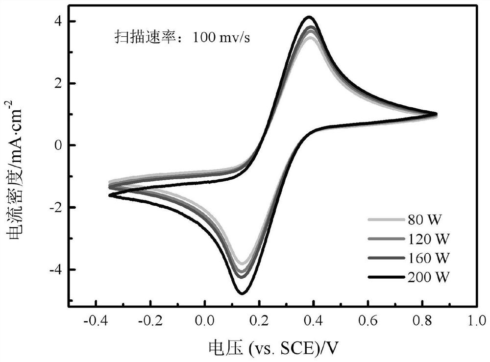
[0044] The prepared positive electrode electrolyte is placed in the ultrasonic generator 5, and the ultrasonic power ranges from 80W to 200W.

[0045] A conductivity meter was used to test the change of the conductivity of the cathode electrolyte under different ultrasonic powers. Test results such as figure 2 As shown, when no ultrasonic wave is added, that is, when the ultrasonic power is 0, the conductivity of the positive electro...

Embodiment 2

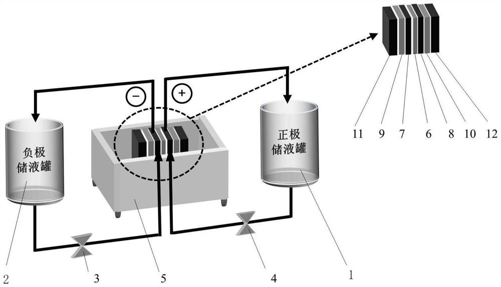
[0059] Prepare positive and negative electrolytes based on deep eutectic solvents, and use FeCl as the positive active material 2 , VCl is selected as the negative electrode active material 3 , the ion exchange membrane 6 uses Nafion212 diaphragm, and the electrode uses GFA series graphite felt electrodes to assemble the flow battery; the assembled flow battery is as follows figure 1 shown.


PUM

PropertyMeasurementUnit
electrical conductivityaaaaaaaaaa

Abstract

The invention discloses a method for improving the transmission performance of a flow battery and a flow battery. According to the method, a deep eutectic solvent electrolyte flow battery is arranged in an ultrasonic generator, so that the ion movement rate of charged ions in electrolyte is improved under the cavitation action of ultrasonic waves, and the conductivity of the flow battery is improved. The flow battery comprises a positive electrode liquid storage tank, a negative electrode liquid storage tank, a first mechanical pump, a second mechanical pump, an ultrasonic generator, an ion exchange membrane, a negative electrode, a positive electrode, a first collector plate, a second collector plate, a first end plate and a second end plate. According to the invention, the chemical and physical characteristics of the deep-eutectic solvent electrolyte are adjusted by adding ultrasonic waves, the diffusion coefficient of ions in the flow battery electrolyte is increased, the problem of low battery power density caused by high viscosity of the existing deep-eutectic solvent electrolyte is effectively solved, and the energy efficiency and power density of the battery are further improved.

Description

technical field [0001] The invention belongs to the technical field of flow batteries in electrochemical energy storage, and in particular relates to a method for improving the transmission performance of a flow battery and a flow battery. Background technique [0002] The concept of a flow battery was first proposed in 1974. Aqueous flow batteries are the most reported in the current literature, and the most studied ones are iron / chromium flow batteries, all-vanadium flow batteries, and bromide / polysulfide flow batteries. In recent years, flow battery technology has become a technology suitable for large-scale energy storage with good prospects due to its advantages of safe and reliable operation, environmental friendliness, flexible design and placement, high energy efficiency, fast start-up and low initial cost. [0003] With the continuous development in recent years, great breakthroughs have been made in the research of water-based flow batteries. A series of water-bas...

Claims


Application Information

Patent Timeline
Patent Type & Authority Applications(China)
IPC IPC(8): H01M8/04276H01M8/18
CPCH01M8/04276H01M8/188Y02E60/50
Inventor 徐谦孙培茁张玮琦马强苏华能
Owner JIANGSU UNIV
Learn More