Medical waste mask treatment device
A treatment device, mask technology, applied in the direction of combustion method, lighting and heating equipment, combustion type, etc., can solve the problems of human body infringement, air pollution, etc.
- Summary
- Abstract
- Description
- Claims
- Application Information
AI Technical Summary
Problems solved by technology
Method used
Image

Examples
Embodiment 1
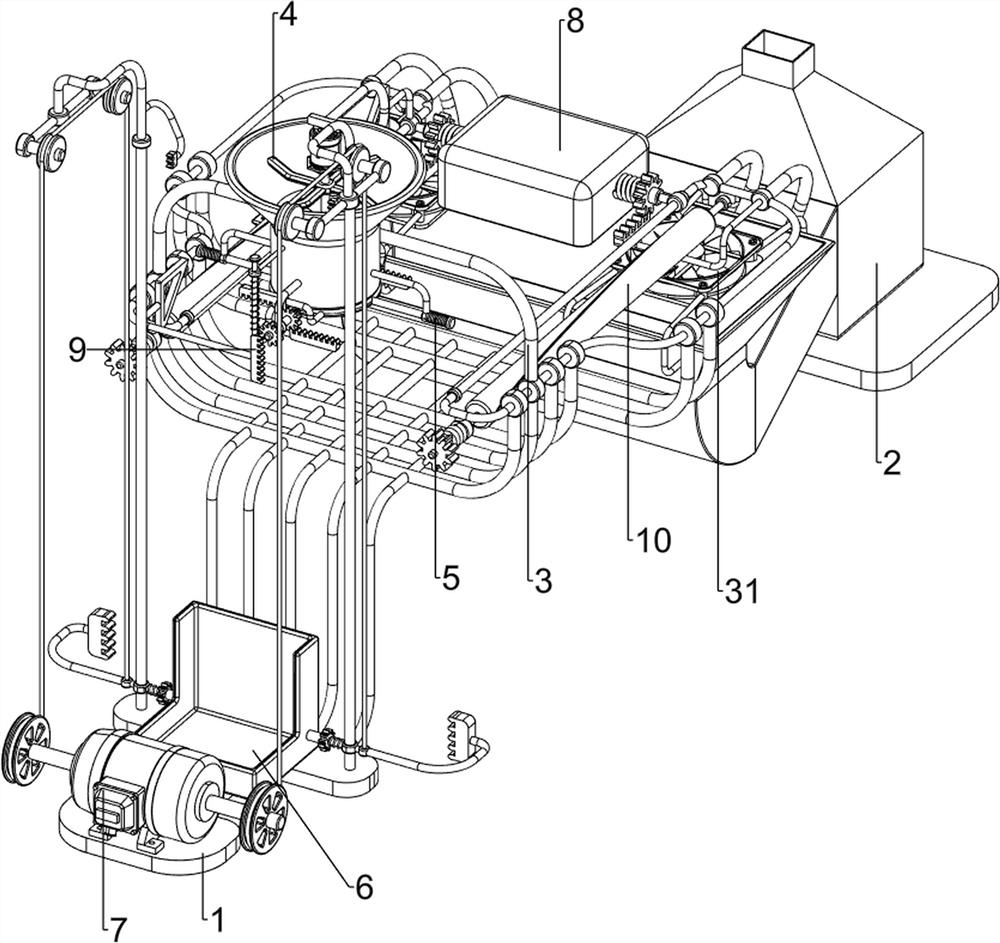
[0081] A treatment device for medical waste masks, such as figure 1 As shown, include base 1, incinerator 2, first support frame 3, fan 31, cutting mechanism 4 and discharge mechanism 5, base 1 and incinerator 2 are placed on the ground, set between base 1 and incinerator 2 There is a first support frame 3, fans 31 are installed on the front and rear sides of the incinerator 2, a cutting mechanism 4 is provided on the first support frame 3, and a discharge mechanism 5 is provided on the cutting mechanism 4.
[0082] When people need to process the waste masks, people place the waste masks in the cutting mechanism 4 and open the cutting mechanism 4 so that the cutting mechanism 4 cuts the waste masks, and the cut waste masks fall on the discharge mechanism 5, when people finish cutting the waste masks, people rotate the discharge mechanism 5, so that the cut waste masks fall on the first support frame 3 through the discharge mechanism 5, and when the cut waste masks fall on the...
Embodiment 2
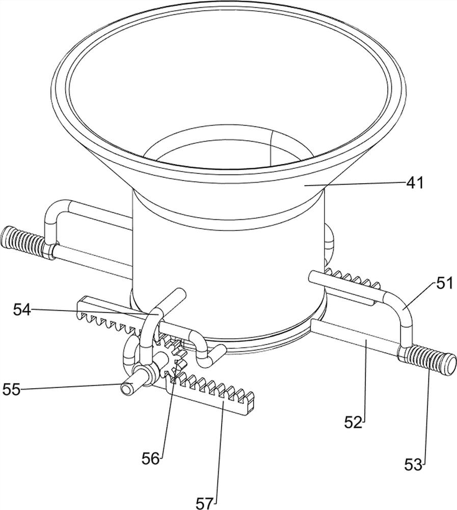
[0084] On the basis of Example 1, such as figure 2 As shown, the cutting mechanism 4 includes a rotating frame 41, a second support frame 42, a first motor 43, a third support frame 44 and a cutting blade 45, and a rotating frame 41 is arranged between the front and rear sides of the first support frame 3 to rotate The right side of the frame 41 outer wall is provided with a second support frame 42, the bottom of the second support frame 42 is equipped with a first motor 43, the inside of the rotating frame 41 is provided with a third support frame 44, and the output shaft of the first motor 43 passes through the third support In the middle of the frame 44, the lower part of the output shaft of the first motor 43 is uniformly connected with a cutting blade 45.
[0085] When people place discarded masks on the rotating frame 41, people turn on the first motor 43, and the output shaft of the first motor 43 drives the cutting blade 45 to rotate, so that the output shaft of the f...
Embodiment 3
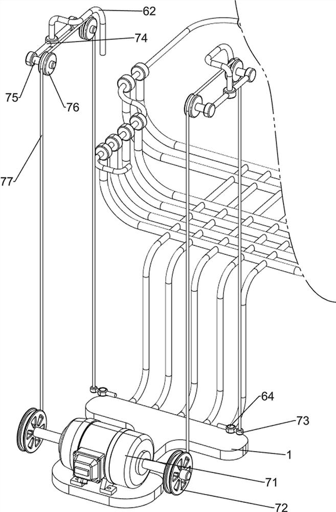
[0087] On the basis of Example 2, such as figure 1 , image 3 , Figure 4 , Figure 5 , Figure 6 , Figure 7 , Figure 8 and Figure 9 As shown, the discharge mechanism 5 includes a fourth support frame 51, a baffle plate 52, a first spring 53, a fifth support frame 54, a first rotating shaft 55, a first gear 56 and a first rack 57, and the rotating frame 41 front and rear Both walls are provided with a fourth support frame 51, and the bottoms of the two fourth support frames 51 are slidingly provided with baffles 52, the two baffles 52 cooperate with the rotating frame 41, and the outer sides of the two baffles 52 are covered with first springs 53, the two ends of the first spring 53 are respectively connected with the baffle plate 52 and the fourth support frame 51, the left and right sides of the rotating frame 41 are provided with the fifth support frame 54, and the two fifth support frames 54 are rotatably provided with the fifth support frame 54. A rotating shaft...
PUM
 Abstract
Description
Claims
Application Information
 - R&D
- Intellectual Property
- Life Sciences
- Materials
- Tech Scout
- Unparalleled Data Quality
- Higher Quality Content
- 60% Fewer Hallucinations
Browse by: Latest US Patents, China's latest patents, Technical Efficacy Thesaurus, Application Domain, Technology Topic, Popular Technical Reports.
© 2025 PatSnap. All rights reserved.Legal|Privacy policy|Modern Slavery Act Transparency Statement|Sitemap|About US| Contact US: help@patsnap.com