


Quick Research
Generate reliable direction feasibility study reports for your R&D in just a few steps.

Technical Q&A
Discover and master advanced knowledge NOW. Basics, ideas, possibilities, all at once.

Find Solutions
As an expert in R&D theories, this can generate solutions to your technical problems instantly.

Evaluate Feasibility
Analyze your overall solution with one click, know your potential R&D risks in advance.

Monitor Landscape
Get weekly tech updates, stay abreast of the latest tech innovations and key insights.
Stamping machine tool with feeding and discharging device
A stamping machine tool and material block technology, which is applied in the direction of feeding device, positioning device, storage device, etc., can solve the problems of inability to clean the mold, reduce the stamping precision and service life of the mold, and sticking of stamping debris, so as to realize automatic loading and unloading , reduce manual input, reduce the effect of damage
- Summary
- Abstract
- Description
- Claims
- Application Information
AI Technical Summary
Problems solved by technology
Method used
Image


Examples
Embodiment 1
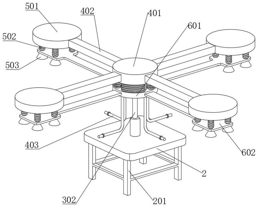
[0053]SeeFigure 1-10 A stamping machine having a upper and lower apparatus, including a pressing machine 1, a stamping machine 1, a pressing machine, an upper and lower material, including a bottom plate 2, a bottom plate 2, a chassis assembly 3, an transposition assembly 3 upper end connection There is a pneumatic assembly 4, the outer end of the pneumatic assembly 4 is connected to the suction assembly 5, and the lower end of the pneumatic assembly 4 is connected to the moving assembly 6 that matches the suction assembly 5, and the rear end of the bottom plate 2 is connected to the controller box; seeFigure 2-5 The pneumatic assembly 4 includes a pneumatic top plate 401, and the upper end of the transposition assembly 3 is fixedly connected to the pneumatic top plate 401. The outer end of the pneumatic top plate 401 is fixedly connected to a plurality of pneumatic billet 402, and the pneumatic branch plate 402 is connected to a main gas pipe. 403. The lower end of the air pipe 403...
Embodiment 2
[0064]SeeFigure 1-10 The same or corresponding components as in Example 1 employ reference numerals corresponding to Embodiment 1, which is simply, and the difference points from Example 1 are described below. This Example 2 differs from the first embodiment in that: seeFigure 9 The moving air bag 603 is distributed between the two air tube 403, and the diameter of the airbag branch 604 is from 0.5 to 0.3 times the air pipe 403. By making the diameter of the airbag branch 604 smaller than the tube of the main trachea 403, the power of the suction assembly 5 is larger than the power of the moving assembly 6, and the mobile component 6 is effectively achieved. It can effectively buffer, reduce the force of the suction assembly 5 in the falling material.
Embodiment 3
[0066]SeeFigure 1-10 The same or corresponding components as in Example 1 employ reference numerals corresponding to Embodiment 1, which is simply, and the difference points from Example 1 are described below. This Example 3 differs from the first embodiment in that: seeFigure 10 , A method of using a stamping machine with a upper and lower apparatus, including the following steps:
[0067]S1. After the pressing machine 1 completes a stamping operation, the controller box controls the transposition assembly 3 to rotate, and the pneumatic assembly 4 is rotated to the upper end of the stamping machine 1, turn off the transfer assembly 3;
[0068]S2. The controller box controls the pneumatic assembly 4 ventilation, so that the suction assembly 5 is filled with the stamping machine tool 1, and clerug the stamping residue on the stamping machine tool 1 workbench;
[0069]S3. The controller box controls the moving assembly 6 and the pneumatic assembly 4, so that the pneumatic assembly 4 is inversi...
PUM
 Abstract
Description
Claims
Application Information
 - R&D Engineer
- R&D Manager
- IP Professional
- Industry Leading Data Capabilities
- Powerful AI technology
- Patent DNA Extraction
Browse by: Latest US Patents, China's latest patents, Technical Efficacy Thesaurus, Application Domain, Technology Topic, Popular Technical Reports.
© 2024 PatSnap. All rights reserved.Legal|Privacy policy|Modern Slavery Act Transparency Statement|Sitemap|About US| Contact US: help@patsnap.com