Biomass combustion boiler

A biomass and boiler technology, applied in the field of biomass combustion boilers, can solve the problems of insufficient utilization of waste heat in the gasification chamber, failure to realize high-temperature carbon waste heat recovery and reuse, and failure to disclose waste gas waste heat recovery and reuse, etc., to achieve Save energy, reduce dust pollution, and save costs

Active Publication Date: 2021-04-23
GUANGXI GUIGANG XIJIANG ENERGY SAVING BOILER
View PDF7 Cites 1 Cited by
  • Summary
  • Abstract
  • Description
  • Claims
  • Application Information

AI Technical Summary

Problems solved by technology

However, the biomass gasification combustion boiler system has the following shortcomings or deficiencies: 1. The waste heat of the gasification chamber furnace body has not been fully utilized; Purification treatment increases the construction cost of the system; 3. The burner has not been improved for biomass gas, and the combustion efficiency is low
Although the patent proposal discloses that after gasification of biofuels, the separation and utilization of gas-fired boilers also recover charcoal at the same time; Recovery and reuse of waste heat from exhaust gas in the post-combustion process

Method used


Image

  • Biomass combustion boiler
  • Biomass combustion boiler
  • Biomass combustion boiler

Examples


Embodiment Construction

[0030]The following will clearly and completely describe the technical solutions in the embodiments of the present invention with reference to the accompanying drawings in the embodiments of the present invention. Obviously, the described embodiments are only part of the embodiments of the present invention, not all of them. Based on the embodiments of the present invention, all other embodiments obtained by persons of ordinary skill in the art without making creative efforts belong to the protection scope of the present invention.

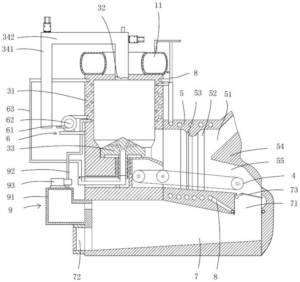
[0031] Such as Figure 1 to Figure 4 As shown, the present invention provides a biomass combustion boiler body 1, including a boiler body 1, a gas combustion chamber 2, a gasification chamber 3, a chain grate 4, an air supply pipeline 6, a preheating water tank 22, and a charcoal recovery chamber 7. The vaporization pipeline 8 and the gas suction pipeline 9, the gas combustion chamber 2 is installed in the boiler body 1, and a furnace arch 5 is pr...


PUM


Abstract

The invention discloses a biomass combustion boiler. The boiler comprises a boiler body, a gas combustion chamber, a gasification chamber, an air supply pipeline, a preheating water tank and a chain grate stoker; the gas combustion chamber is arranged in the boiler in a penetrating mode, a boiler arch is arranged between the gasification chamber and the gas combustion chamber, the gas combustion chamber communicates with a waste gas exhaust pipeline, the two ends of the air supply pipeline communicate with the gasification chamber and the gas combustion chamber correspondingly, and the air supply pipeline surrounds the peripheral wall of the gasification chamber; the preheating water tank is arranged on the outer wall of the waste gas exhaust pipeline and communicates with the boiler; a carbon recovery chamber is arranged below the boiler arch and the gasification chamber, and a carbon inlet is formed in the position, located at the output tail end of the chain grate stoker, of the carbon recovery chamber; a vaporizing pipeline surrounds the peripheral wall of the boiler arch or the gasification chamber, the water inlet end of the vaporizing pipeline communicates with the preheating water tank, and the steam outlet end of the vaporizing pipeline is mounted in the carbon recovery chamber; and the carbon recovery chamber communicates with the gas combustion chamber through a gas suction pipeline. The combustion boiler can recover high-temperature waste heat of carbon production, and also realizes waste heat recovery of gas combustion waste gas.

Description

technical field [0001] The invention relates to the field of biomass burning boilers, in particular to a biomass burning boiler. Background technique [0002] At present, there are two ways to burn biomass fuel at home and abroad; one is to directly put biomass fuel into the boiler for combustion; this method is basically the same as the traditional coal burning method, so the furnace is wide, Tall, large boiler leakage coefficient, scattered blast, etc., are not conducive to the combustion of biomass pellet fuel, low furnace temperature during use, large flue gas volume, black smoke, and large fuel heat loss, low boiler thermal efficiency, unfavorable for environmental protection, etc. question. The other is to burn and crack the biomass to gasify to obtain combustible gas, and then burn the combustible gas to heat the boiler. This combustion method is the same as the technical solution disclosed in a biomass gasification combustion boiler system with patent number 201310...

Claims


Application Information

Patent Timeline
Patent Type & Authority Applications(China)
IPC IPC(8): F24H1/34F24H9/18F23B10/02F23J15/06C10J3/86
CPCF24H1/34F24H9/2057F23B10/02F23J15/06C10J3/86Y02E20/30
Inventor 叶逢春钟钊奇林举华莫伟华
Owner GUANGXI GUIGANG XIJIANG ENERGY SAVING BOILER
Why Eureka
Try Eureka