Steel structure metal pipe fitting drilling equipment and drilling method thereof

A technology for metal pipe fittings and processing equipment, which is applied in the direction of metal processing equipment, drilling/drilling equipment, metal processing machinery parts, etc., and can solve the problem of not being suitable for clamping and fixing metal pipe fittings, not being able to effectively discharge outwards, and not being able to position holes Accurate guarantee and other issues, to achieve the effect of increasing the movable range, improving the drilling quality, and improving the processing accuracy

Active Publication Date: 2021-04-13
陕西以琳建设工程有限公司
View PDF4 Cites 1 Cited by
  • Summary
  • Abstract
  • Description
  • Claims
  • Application Information

AI Technical Summary

Problems solved by technology

[0003] At present, metal pipe fittings are widely used in all walks of life, and metal pipe fittings need to be drilled before use to meet their use requirements. The existing drilling processing methods are mostly manual clamping of metal pipe fittings, and then manual Manual drilling, but the current clamps for metal pipe fittings cannot be clamped and fixed stably, and are not suitable for clamping and fixing metal pipe fittings of different diameters, resulting in limitations in drilling and clamping of metal pipe fittings, and after drilling for metal pipes, A large amount of metal debris is mixed in the pipe and cannot be effectively discharged, and the traditional drilling jig releases the jig after drilling a hole, and manually rotates the pipe to drill another drilling part. holes, but manual movement will inevitably cause the position deviation of the pipe fittings, so that the drilled holes cannot be accurately guaranteed to be on the same ring line, and the machining accuracy is low. Therefore, the present invention provides a steel structure Drilling processing equipment for metal pipe fittings and drilling method thereof

Method used


Image

  • Steel structure metal pipe fitting drilling equipment and drilling method thereof
  • Steel structure metal pipe fitting drilling equipment and drilling method thereof
  • Steel structure metal pipe fitting drilling equipment and drilling method thereof

Examples


Embodiment Construction

[0031] In order to make the technical means, creative features, goals and effects achieved by the present invention easy to understand, the present invention will be further elaborated below in conjunction with specific drawings. It should be noted that, in the case of no conflict, the embodiments and Features in the embodiments can be combined with each other.

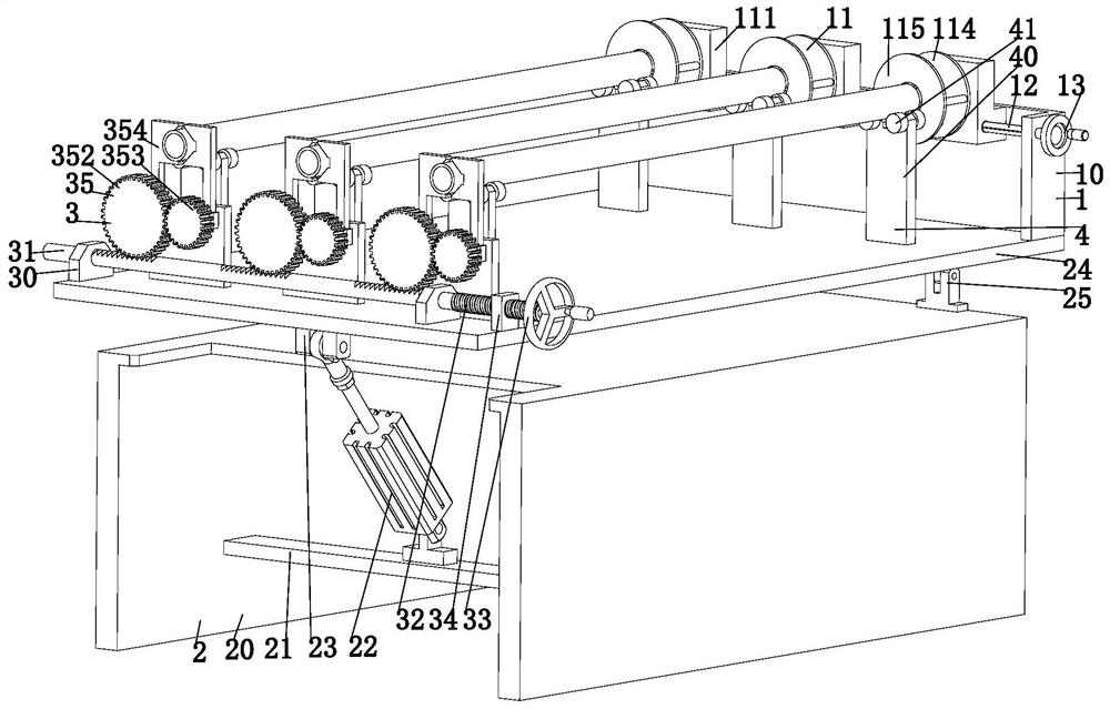
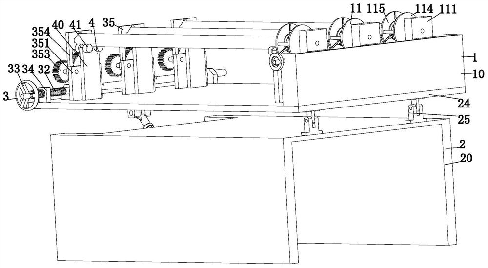
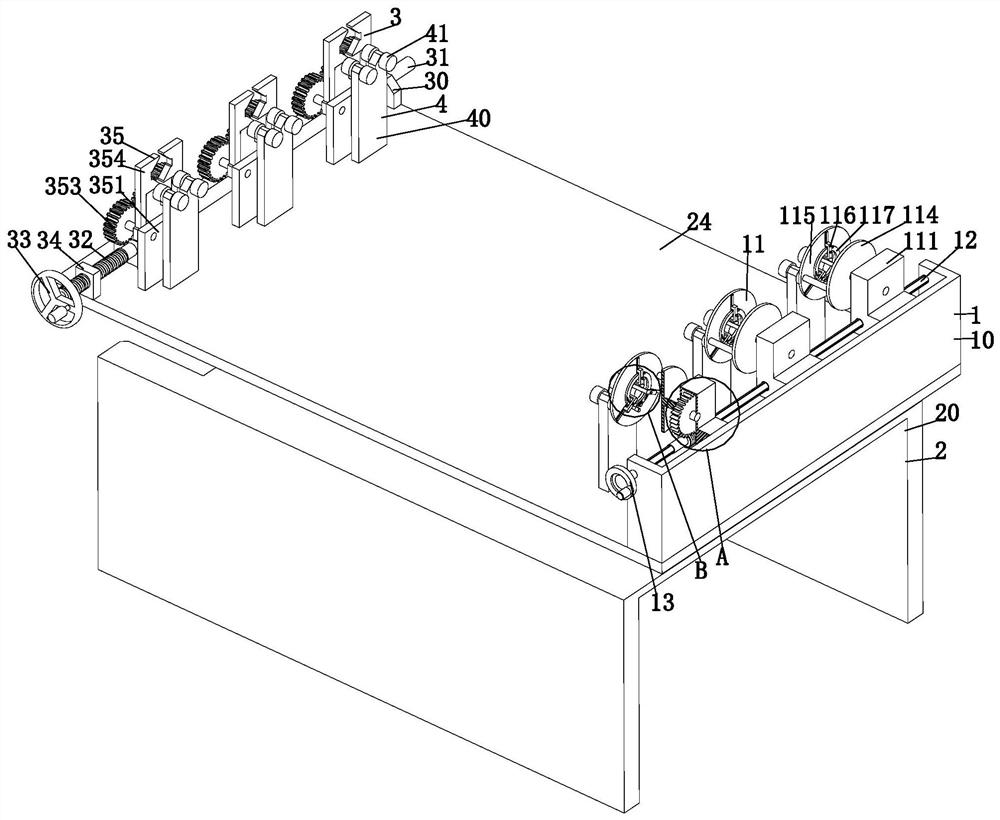
[0032] Such as Figure 1 to Figure 8 As shown, a steel structure metal pipe fitting drilling processing equipment includes a clamping mechanism 1, a chip removal mechanism 2, a clamping mechanism 3 and a holding mechanism 4, and a clip is installed on the left end surface of the chip removal mechanism 2 Mechanism 3, a clamping mechanism 1 is installed on the right end surface of the chip removal mechanism 2, and a lifting mechanism 4 is arranged between the clamping mechanism 3 and the clamping mechanism 1, and the lifting mechanism 4 is symmetrical Installed on the chip removal mechanism 2; where:

[0033] The supp...


PUM


Abstract

The invention provides steel structure metal pipe fitting drilling equipment and a drilling method thereof. The steel structure metal pipe fitting drilling equipment comprises a clamping mechanism, a chip removal mechanism, a fixture mechanism and supporting and placing mechanisms, wherein the fixture mechanism is arranged on the left side end surface of the chip removal mechanism, the clamping mechanism is arranged on the right side end surface of the chip removal mechanism, the supporting and placing mechanisms are arranged between the fixture mechanism and the clamping mechanism, and symmetrically arranged on the chip removal mechanism. The steel structure metal pipe fitting drilling equipment solves the problems that an existing metal pipe fitting clamp cannot stably clamp and fix metal pipe fittings and cannot be suitable for clamping and fixing the metal pipe fittings with different diameters, so that metal pipe fitting drilling clamping has limitation, metal chips mixed inside the pipes cannot be discharged outwards after the pipe fittings are drilled, and after one hole is drilled through a traditional drilling clamp, the pipe fittings are rotated manually, so that the other drilling part is drilled, however, the positions of the pipe fittings deviate due to manual movement so that the hole positions cannot be accurately located on the same loop line, and the machining precision is low.

Description

technical field [0001] The invention relates to the technical field of drilling, in particular to a drilling processing equipment for metal pipe fittings of steel structure and a drilling method thereof. Background technique [0002] Steel structure is a structure composed of steel materials, which is one of the main types of building structures; the structure is mainly composed of steel beams, steel columns, steel pipes, steel trusses and other components made of section steel and steel plates, etc. Welds, bolts or rivets are usually used to connect, and steel structure metal pipe fittings are widely used because of their strong ability to resist plastic deformation and fracture under the action of external force, high strength, light weight, good overall rigidity and strong deformation ability. It is used in many fields, such as petroleum, chemical industry, medical treatment, food, light industry, mechanical instrumentation and other industrial pipelines and mechanical st...

Claims


Application Information

Patent Timeline
Patent Type & Authority Applications(China)
IPC IPC(8): B23B41/02B23Q3/06B23Q11/00
CPCB23B41/02B23Q3/064B23Q11/0042Y02P70/10
Inventor 任玉晴谢煜
Owner 陕西以琳建设工程有限公司
Why Eureka
Try Eureka