
Treatment method of high-water-content oil sludge

A treatment method and technology for water-containing oil, which can be used in water/sludge/sewage treatment, sludge treatment, immiscible solvent sludge treatment, etc., and can solve the problems of complex composition, large area occupied by microbial methods, and limited treatment. , to achieve the effect of good drying effect, abandoning re-pollution and significant resource utilization

Active Publication Date: 2021-03-26
SHENZHEN KELADA FINE CHEM CO LTD
View PDF9 Cites 0 Cited by
  • Summary
  • Abstract
  • Description
  • Claims
  • Application Information

AI Technical Summary

Problems solved by technology

Solvent extraction method, a large amount of extraction agent is used in the solvent extraction process, the cost is high, and the equipment maintenance cost, depreciation cost and treatment cost in the process are high; the centrifugal dehydration method is only a pure reduction method, because the water in the sludge is mainly It is in an emulsified state, so it is difficult to dehydrate, and it cannot really achieve the purpose of treating high water content sludge
The thermal analysis method also has the problems of high energy consumption, waste gas generation, etc., and also has the problems of flammability and explosion, and the equipment is easy to coke and block.
The various chemicals used in the thermochemical demulsification method have a certain effect on simple high-water-content oil sludge, but have no obvious demulsification effect on high-water-content oil sludge with complex components, high viscosity, more colloids, and more asphaltene
The microwave treatment method is currently only studied in the laboratory, and it also has the disadvantages of high energy consumption and high safety risks at the operation site.
The microbial method occupies a large area, has a long treatment period, is restricted by the ambient climate temperature, and can only treat oil sludge with an oil content of less than 5%, so the treatment is limited
[0005] In recent years, some domestic enterprises have adopted sulfuric acid acidification treatment followed by drying and weight reduction to treat oil sludge, but they cannot continue to operate due to safety risks such as hydrogen sulfide production and low-flash point substances that are flammable and explosive.
Generally speaking, there is no relatively mature treatment method in China, especially the treatment method that can achieve long, stable, safe, full and optimal operation.

Method used


Image

  • Treatment method of high-water-content oil sludge

Examples


Embodiment 1

[0036] The sample treated in this example is a high water content oil sludge (water content 88.74%, oil content 7.79%, solid content 3.47%) of a petrochemical plant in Lanzhou, and the phase transfer agent is (by weight): diethylene glycol dimethyl Ether 80%, mixed xylene 20%, propylene glycol polyether 1.5% and p-phenylenediamine 0.5%.

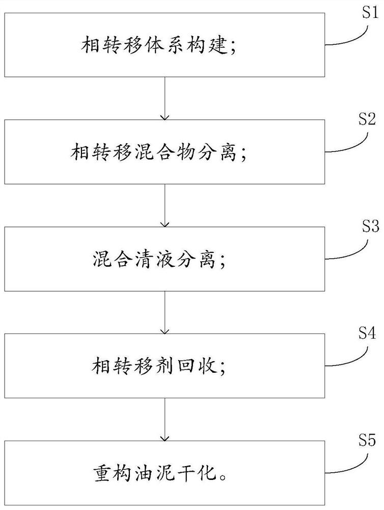
[0037] In this example S1, 300 g of the above-mentioned high-water-content sludge and 150 g of special phase transfer agent were weighed and added to a 1000 ml open container, the temperature was raised to 50 ° C, put into a homogenizer and homogenized at a speed of 5000 rpm for 5 minutes to obtain a phase transfer mixture;

[0038] In this example S2, 450 g of the phase transfer mixture containing the phase transfer agent prepared in S1 was centrifuged at room temperature to obtain 264.4 g of oil, water, and agent mixed supernatant and 183.2 g of reconstituted sludge.

[0039] In this example S3, the mixed clear liquid obtained in S2 was lef...

Embodiment 2

[0044] The sample treated in this example is a high water content oil sludge (water content 68.58%, oil content 16.81%, solid content 14.61%) of a petrochemical plant in Jiujiang, and the phase transfer agent is (by weight): diethylene glycol dimethyl Ether 70%, mixed xylene 30%, propylene glycol polyether 0.5% and p-phenylenediamine 0.5%.

[0045] In this example S1, 300 g of the above-mentioned high water content sludge and 150 g of special phase transfer agent were weighed and added into a 1000 ml open container, and placed in a homogenizer at room temperature to homogenize for 5 minutes at a rotation speed of 5000 rpm to obtain a phase transfer mixture;

[0046] In this example S2, 450 g of the phase transfer mixture containing the phase transfer agent prepared in S1 was centrifuged at room temperature to obtain 229 g of oil, water, and agent mixed supernatant and 217.5 g of reconstituted sludge.

[0047] In this example S3, the mixed clear liquid obtained in S2 was heated...

Embodiment 3

[0052] The sample treated in this example is a high water content oil sludge (water content 88.74%, oil content 7.79%, solid content 3.47%) of a petrochemical plant in Lanzhou, and the phase transfer agent is (by weight): diethylene glycol dimethyl Ether 60%, mixed xylene 40%, propylene glycol polyether 1.5% and p-phenylenediamine 0.5%.

[0053] In this example S1, 300 g of the above-mentioned high-water-content sludge and 150 g of special phase transfer agent were weighed and added to a 1000 ml open container, the temperature was raised to 50 ° C, put into a homogenizer and homogenized at a speed of 5000 rpm for 5 minutes to obtain a phase transfer mixture;

[0054] In this example S2, 450 g of the phase transfer mixture containing the phase transfer agent prepared in S1 was centrifuged at room temperature to obtain 262.4 g of oil, water, and agent mixed supernatant and 184.2 g of reconstituted sludge.

[0055] In this example S3, the mixed clear liquid obtained in S2 was lef...


PUM


Abstract

The invention is applicable to the field of high-water-content oil sludge treatment, and provides a treatment method of high-water-content oil sludge, wherein the treatment method comprises the following steps: S1, constructing a phase transfer system; S2, separating a phase transfer mixture; S3, separating a mixed clear liquid; S4, recovering a phase transfer agent; and S5, drying reconstructed oil sludge. The defects in the prior art are overcome, and the pollution influence of oil sludge on the environment can be reduced; and secondly, oil and water in the oil sludge can be recycled, and the purpose of resource recycling value is achieved.

Description

technical field [0001] The invention belongs to the field of high water content oil sludge treatment, in particular to a treatment method of high water content oil sludge. Background technique [0002] Refinery sludge mainly refers to the "three sludges" of refinery wastewater, including the bottom sludge of grease traps, scum in air flotation tanks, residual activated sludge in biochemical tanks, and a small amount of bottom sludge in sewage tanks generated during wastewater treatment in refineries. Improper disposal of oil sludge will cause a certain degree of harm to the environment. At present, many enterprises still use the method of limited stacking of foreign transport after initial settlement and dehydration. However, as the environmental protection laws and regulations of countries around the world become more stringent, the demand for sludge reduction, stabilization, and recycling is getting higher and higher. [0003] The organic matter in refinery sludge has com...

Claims


Application Information

Patent Timeline
Patent Type & Authority Applications(China)
IPC IPC(8): C02F11/00C02F101/32
CPCC02F11/002C02F2101/32C02F2303/06
Inventor 段征宇胡幼元张运晟雷电
Owner SHENZHEN KELADA FINE CHEM CO LTD
Learn More