
Intelligent braze coating device and braze coating method

An intelligent brazing and brazing coating technology, applied in tin feeding devices, auxiliary devices, metal processing, etc., can solve the lack of monitoring of coating morphology and temperature field, the inability to achieve real-time optimization of process parameters, and the inaccurate control of coating thickness And other problems, to achieve the effect of improving coating quality and braze coating accuracy, small dilution and smooth surface

Active Publication Date: 2021-03-26
NORTH CHINA UNIV OF WATER RESOURCES & ELECTRIC POWER
View PDF12 Cites 2 Cited by
  • Summary
  • Abstract
  • Description
  • Claims
  • Application Information

AI Technical Summary

Problems solved by technology

A brazing strengthening method for thermal spray coating on the surface of metal materials (201110040723.0), using thermal spraying technology to prepare a brazing strengthening coating on the metal surface, the strength is greater than 250MPa; a vacuum brazing cermet composite coating on the surface of titanium alloy The method (201410472749.6), adopts the steps of substrate pretreatment, powder pretreatment and vacuum brazing, the surface hardness and wear resistance of titanium alloy are improved, and it can withstand large loads and severe friction; a central powder feeding can expand Multi-beam laser cladding head and its application (201711184987.7), discloses a supporting device for laser processing equipment, which is used in the fields of metal surface cladding, laser repair, laser welding, etc.; It requires a lot of manual operations, especially in the feeding process, most of which use pre-set solder, which seriously reduces the efficiency of coating preparation
In addition, there is a lack of monitoring of the coating morphology and temperature field, and the coating thickness cannot be accurately controlled, and the goal of real-time optimization of process parameters cannot be achieved.

Method used


Image

  • Intelligent braze coating device and braze coating method

Examples


Embodiment 1

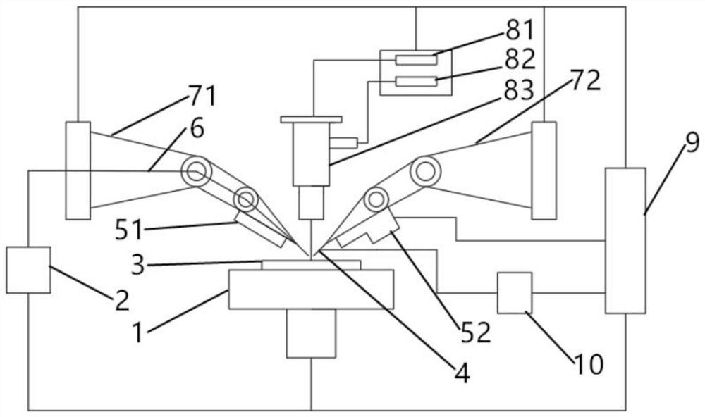
[0026] An intelligent brazing device, including a movable workbench 1, a wire feeding mechanism 2, two industrial robots, a coating temperature field monitoring device, a coating profile monitoring device, a high-energy beam generator 10 and a control system 9; the mobile working Table 1 can move freely in the X-Y plane. The two industrial robots, the coating temperature field monitoring device and the coating profile monitoring device are all set above the movable worktable 1, and the workpiece is placed on the movable worktable 1. , the robot 71 in the two industrial robots is used to provide wire solder, the robot 72 is used to provide the heat source for brazing coating, the wire feeding mechanism 2 transports the wire or tubular solder 6 for the robot 71, and the high-energy beam emitter 10 passes the high-energy beam Emitting head 4 provides heat source for robot 72; Described control system 9 is connected with movable workbench 1, wire feeding mechanism 2, two industrial...


PUM

PropertyMeasurementUnit
strengthaaaaaaaaaa

Abstract

The invention relates to an intelligent braze coating device and a braze coating method. The intelligent braze coating device comprises a movable workbench, a wire feeding mechanism, two industrial robots, a coating temperature field monitoring device, a coating contour monitoring device, a high-energy beam generator and a control system, wherein the two industrial robots, the coating temperaturefield monitoring device and the coating contour monitoring device are all arranged above the movable workbench, one of the two industrial robots is used for providing wire brazing filler metal, the other one of the two industrial robots is used for providing a braze coating heat source, the wire feeding mechanism is used for conveying wire-shaped or tubular brazing filler metal to the robots, anda high-energy beam emitter provides a heat source for the robots through a high-energy beam emitting head. A prepared coating is a cladding layer which is smooth in surface, good in combination with base metal, free of crack defects and compact in structure. From the perspective of equipment platform development, the problems that manual braze coating is poor in stability and uneven in coating thickness are solved.

Description

technical field [0001] The invention relates to the field of welding technology, in particular to an intelligent brazing device and a brazing method. Background technique [0002] Brazing is essentially a special kind of brazing, which relies on the molten solder or the liquid phase formed by the diffusion between the surface of the base metal and the solder, spreads the base metal under capillary action, and interacts. Coating preparation means. The prepared coating has the advantages of high bonding strength, small thermal stress, smooth surface and high precision. Traditional brazing methods such as induction brazing and furnace brazing require a lot of manual operations. At the same time, during the coating preparation process, there is a lack of monitoring of coating morphology and temperature field, and the quality of the obtained coating needs to be improved. Therefore, the research and development of intelligent brazing equipment, especially the real-time monitorin...

Claims


Application Information

Patent Timeline
Patent Type & Authority Applications(China)
IPC IPC(8): B23K3/00B23K3/06B23K3/08
CPCB23K3/00B23K3/063B23K3/08
Inventor 王星星武胜金李帅杜全斌温国栋彭进贾连辉崔大田倪增磊金向杰李刚
Owner NORTH CHINA UNIV OF WATER RESOURCES & ELECTRIC POWER
Learn More