
Self-flowing drainage pressure-limiting anti-floating structure and construction method

A self-flowing drainage and construction method technology, applied in infrastructure engineering, protection devices, buildings, etc., can solve the problems of engineering anti-floating design, such as amazing waste, large energy consumption, and water overflow in sump pits, so as to save groundwater resources, Enhance the anti-floating ability and ensure the effect of sealing

Pending Publication Date: 2020-12-29
CHINA CONSTR EIGHT ENG DIV CORP LTD
View PDF0 Cites 4 Cited by
  • Summary
  • Abstract
  • Description
  • Claims
  • Application Information

AI Technical Summary

Problems solved by technology

[0003] However, the existing active anti-floating technology mainly has the following problems: 1) The sump pit is arranged in the basement, which causes the basement to be humid, and there is a risk of water overflow in the sump pit; 2) The drainage pipe passes through the waterproof layer, making construction difficult. It is easy to seep water at the joints; 3) Continuous pumping and drainage during the operation period consumes a lot of energy; 4) Excessive drainage of groundwater causes surrounding surface settlement and damage to nearby buildings; 5) It is impossible to monitor the building structure to provide anti-buoyancy, so it can only be conservative. Variable loads and side wall frictional resistance are negligible, resulting in an astonishing waste of some engineering anti-floating designs; 6) Structural damage caused by poor drainage

Method used


Image

  • Self-flowing drainage pressure-limiting anti-floating structure and construction method
  • Self-flowing drainage pressure-limiting anti-floating structure and construction method
  • Self-flowing drainage pressure-limiting anti-floating structure and construction method

Examples


Embodiment Construction

[0034] Embodiments of the present invention are described below through specific examples, and those skilled in the art can easily understand other advantages and effects of the present invention from the content disclosed in this specification. The present invention can also be implemented or applied through other different specific implementation modes, and various modifications or changes can be made to the details in this specification based on different viewpoints and applications without departing from the spirit of the present invention.

[0035] The present invention will be described in further detail below in conjunction with the accompanying drawings and specific embodiments.

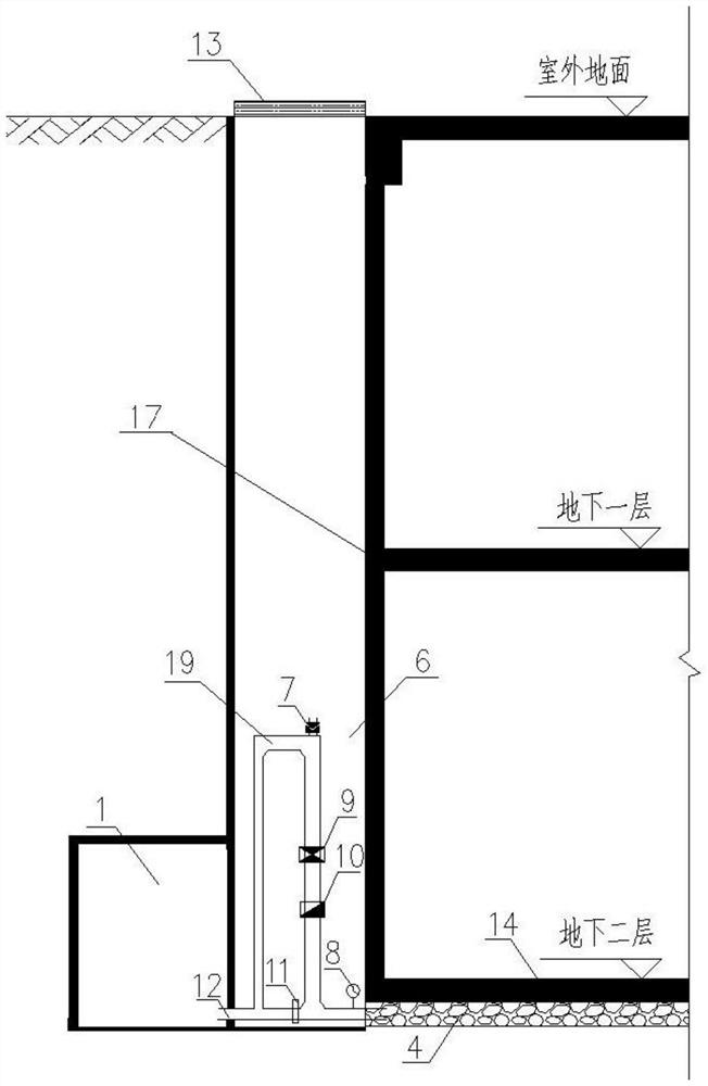
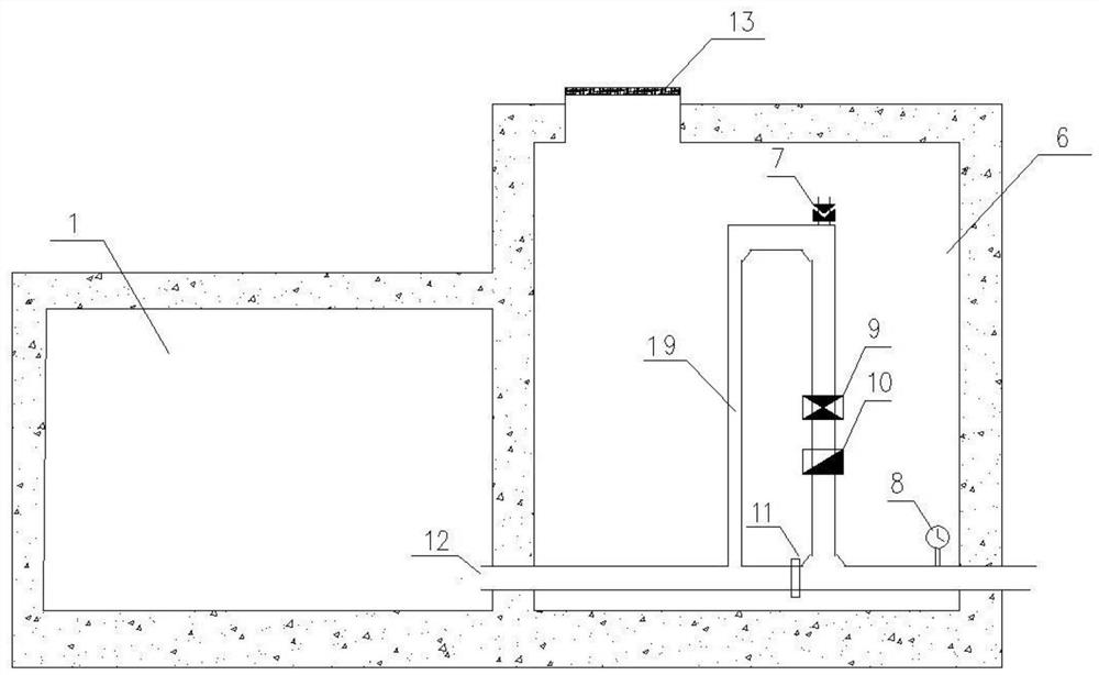
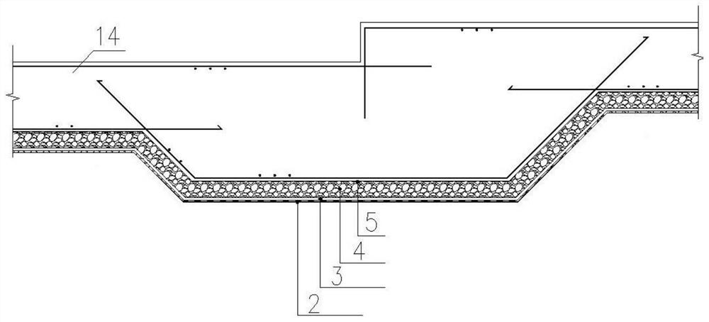
[0036] Such as figure 1 with figure 2 As shown, as an optional embodiment, a self-flowing drainage pressure-limiting anti-floating structure is composed of a permeable system, a water collection system, a drainage system and a monitoring and control system; the permeable system filters the ...


PUM

PropertyMeasurementUnit
Particle sizeaaaaaaaaaa
Thicknessaaaaaaaaaa

Abstract

The invention discloses a self-flowing drainage pressure-limiting anti-floating structure and a construction method. The self-flowing drainage pressure-limiting anti-floating structure is an active anti-floating structure composed of a water permeation system, a water collection system, a drainage system and a monitoring control system. The permeation system filters soil particles in a soil layerto gather pressure water into the water collection system, the pressure water is guided into the drainage system, the monitoring control system regulates and controls drainage in real time according to the relation between resistance and water buoyancy and the substrate floating displacement, a substrate pressure water head is controlled, and the pressure water is drained to a municipal pipe network or a water storage pool through gravity flow pipelines arranged by using the site terrain altitude difference; and the anti-floating structure is arranged outside a waterproof layer of an underground building and is convenient to construct and maintain, and dynamic balance of the water buoyancy and resistance is achieved. The self-flowing drainage pressure-limiting anti-floating structure has the advantages of being effective in anti-floating, simple in construction, economical and environmentally friendly, the problems of safety, sustainable development and environmental protection faced by underground structure anti-floating are effectively solved, and powerful technical support is provided for underground space development.

Description

technical field [0001] The invention relates to the technical field of construction engineering, in particular to an artesian drainage pressure-limiting anti-floating structure and a construction method. Background technique [0002] With the continuous development and utilization of urban underground space, accidents of floating basements of underground buildings / structures occur frequently, causing great social impact and economic losses. How to economically and effectively solve the problem of anti-floating of underground structures has become a hot spot and one of the key points in the process of underground space development. At present, most countries adopt "anti-floating" design methods for the anti-floating design of underground structures. For example, using the method of increasing self-weight, anti-lift piles or anti-lift anchors and other anti-floating structures, the cost is too high and there are safety risks. Drainage pressure limiting technology adopts the i...

Claims


Application Information

Patent Timeline
IPC IPC(8): E02D31/12E02D19/06
CPCE02D19/06E02D31/12
Inventor 修彦吉李洪然姜安庆杜其忠章彰谢忠行
Owner CHINA CONSTR EIGHT ENG DIV CORP LTD
Learn More