
IGCC combined cycle power generation method for co-production of fuel oil and natural gas

A combined cycle power generation and natural gas technology, which is applied in the direction of combined combustion mitigation, combustible gas production, granular/powdered fuel gasification, etc., can solve problems such as single product target, underutilization of element H, and low energy conversion efficiency

Active Publication Date: 2020-12-25
成都聚实节能科技有限公司
View PDF4 Cites 0 Cited by
  • Summary
  • Abstract
  • Description
  • Claims
  • Application Information

AI Technical Summary

Problems solved by technology

[0010] ①The product target is single, either power generation, oil production, or synthetic natural gas, only one of them can be chosen;
[0011] ②Coal gasification into CO+H 2 , especially the entrained bed coal gasification process consumes too much oxygen, resulting in high investment in the coal gasification system including oxygen production, and low energy conversion efficiency, which is only about 66%;
[0012] ③Especially 5% H in coal is forced to consume heat to become elemental H in the high-temperature gasification of IGCC 2 element, and finally burned in the IGCC combustion engine; in the synthesis process of coal to fuel oil and natural gas, up to 35%-40% of the H element must be converted into water H 2 O, not only the element H is not fully utilized, but also makes the generation of H 2 The vast majority (about 66%) of the huge reaction heat of O is forced to become non-recoverable condensation latent heat and exhausted to the atmosphere. Even if it is recovered as electric energy, expensive investment in boilers, steam turbines, motors and other ancillary devices will be paid.

Method used


Image

  • IGCC combined cycle power generation method for co-production of fuel oil and natural gas
  • IGCC combined cycle power generation method for co-production of fuel oil and natural gas
  • IGCC combined cycle power generation method for co-production of fuel oil and natural gas

Examples


Embodiment Construction

[0134] 1. First complete the calculation of material, heat, and power balance, and then complete the design of process, equipment, layout, and piping;

[0135] 2. Site leveling and water, electricity, gas, road and communication network construction;

[0136] 3. Equipment foundation, plant construction, equipment installation, process piping, fire protection, safety and environmental protection facilities construction;

[0137] 4. Debugging of anti-corrosion and heat preservation, electrical instrument control system, test run of water supply and circulating cooling water system, start-up and operation;

[0138] 5. Process equipment cleaning, individual test run, linkage test run; air separation, steam boiler test run, start-up, oxygen and steam output;

[0139] 6. Coal gas furnace is added to start operation, water gas is produced, and CO conversion catalyst is heated up;

[0140] 7. CO conversion, PSA desulfurization and decarbonization separation put into operation, hydroge...


PUM


Abstract

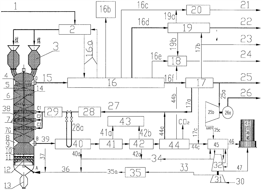
The invention discloses an IGCC combined cycle power generation method for co-production of fuel oil and natural gas. The O2 consumption of coal gasification is greatly reduced by adopting pressurizedmoving bed coal gasification; in the coal gasification process, most of hydrogen elements in the coal directly generate coal tar and methane; the coal tar is hydrogenated to generate fuel oil; residual semicoke is extracted from coal tar, and direct hydromethanation is carried out to produce synthetic natural gas SNG; SNG is used as fuel, an NGCC combined cycle unit is used for electric power production, and an IGCC combined cycle power generation system for co-production of fuel oil and natural gas is formed; residual coke left after hydromethanation is gasified to produce H2 required by adding H2 into coal and H2 required by adding H2 into coal tar; gas turbine tail gas is used for converting low-heating-value tail gas exhausted by a water gas hydrogen production process into power steam through a waste heat boiler, the power steam is used as process steam after driving a steam turbine, and therefore clean, efficient and low-cost co-production of fuel oil and natural gas is achievedwhile IGCC combined cycle power generation is achieved.

Description

technical field [0001] The invention belongs to the field of coal-fired power generation, and in particular relates to the technology and equipment of IGCC integrated coal gasification combined cycle power generation using coal as fuel. Background technique [0002] The traditional IGCC integrated coal gasification combined cycle power generation originated in the 1970s. However, because the IGCC technology uses entrained-bed high-temperature coal gasification with pulverized coal particle size less than 0.1mm, not only raw coal with low ash content is required, but also the system’s coal preparation process has high technical requirements, large equipment investment, and high energy consumption; [0003] Especially the coal gasification oxygen consumption per unit of electric energy is as high as 0.2Nm 3 / kwh, not only greatly increases the energy consumption of power generation, but also increases the cost of IGCC due to the high investment cost of the oxygen generation s...

Claims


Application Information

Patent Timeline
IPC IPC(8): C10J3/48C10J3/72C10J3/82C10J3/84C10L3/10C10G45/02
CPCC10J3/48C10J3/72C10G45/02C10J3/721C10J3/84C10J3/82C10L3/10Y02E20/18Y02P20/129
Inventor 李宁李开建
Owner 成都聚实节能科技有限公司
Learn More