
On-chip antenna based on glass through hole array

A technology of through-glass holes and on-chip antennas is applied to antennas, antenna coupling, antenna components, etc., which can solve the problems of reducing chip reliability, increasing the complexity of chip manufacturing process, reducing the degree of system miniaturization, etc. Improve radiation directivity, radiation gain, and the effect of low dielectric loss

Active Publication Date: 2020-11-27
NINGBO UNIV
View PDF11 Cites 2 Cited by
  • Summary
  • Abstract
  • Description
  • Claims
  • Application Information

AI Technical Summary

Problems solved by technology

Document 2 (E. Ojefors, Micromachined loop antennas on low resistivity silicon substrate. IEEE Trans. Antenna and Propagation, 2006.) uses micromachining technology to remove part of the lossy substrate, thereby reducing substrate loss and increasing antenna gain, but slightly The introduction of mechanical processing methods increases the process complexity of chip manufacturing, and the existence of cavities in the substrate also reduces the reliability of the chip
Document 3 (I. Sarkaset al., A fundamental frequency 120GHz SiGe BiCMOS distance sensor within integrated antenna, IEEE Trans. Microwave Theory and Technology, 2012.) fabricates a silicon lens on the substrate on the back of the antenna, so that the antenna energy can radiate out through the lens , to improve the antenna gain, but the lens size is generally larger than the chip size, and the introduction of the lens will reduce the miniaturization of the system

Method used


Image

  • On-chip antenna based on glass through hole array
  • On-chip antenna based on glass through hole array
  • On-chip antenna based on glass through hole array

Examples


Embodiment Construction

[0028] The present invention will be further described in detail below in conjunction with the accompanying drawings and embodiments.

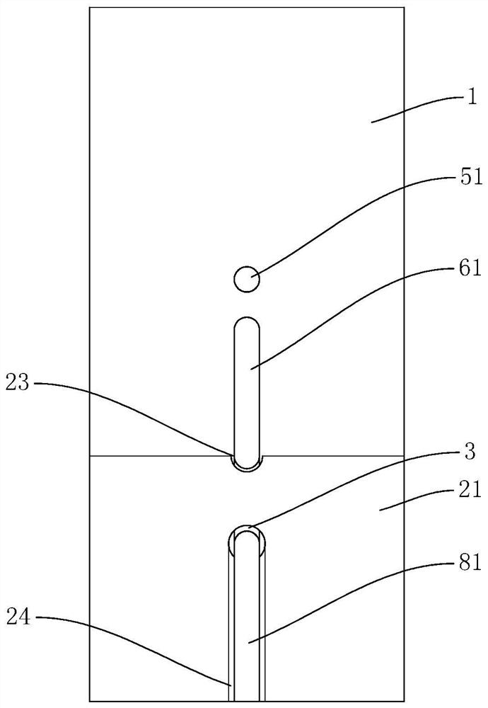
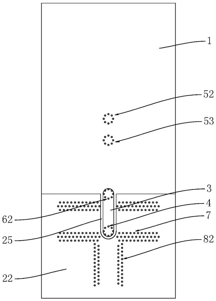
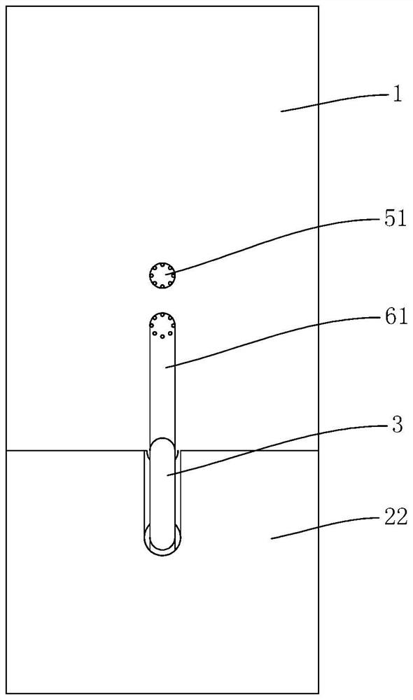
[0029] The on-chip antenna based on the through-glass via array of the embodiment, such as Figure 1 ~ Figure 4As shown, it includes a glass dielectric substrate 1, a director, a monopole antenna radiator, a reflective wall, a top truncated metal floor 21, a bottom truncated metal floor 22, a bottom metal strip 3, a connecting through-glass hole array 4 and a common ground. Surface waveguide feeding structure; the director includes a top metal circular plate 51, a first through-glass hole array 52 and a second through-glass hole array 53, and the monopole antenna radiator includes a top-layer metal strip 61 and a third through-glass hole Array 62, the reflective wall includes four sets of fourth through-glass hole arrays 7, the grounded coplanar waveguide feed structure includes strip-shaped metal feeders 81 and two sets of fifth through-glass...


PUM

PropertyMeasurementUnit
frequencyaaaaaaaaaa

Abstract

The invention discloses an on-chip antenna based on a glass through hole array. The on-chip antenna comprises a glass dielectric substrate, a director, a monopole antenna radiator, a reflecting wall,a top-layer cut-off metal floor, a bottom-layer cut-off metal floor, a bottom-layer metal strip, a connecting glass through hole array and a grounding coplanar waveguide feed structure. According to the on-chip antenna based on the glass through hole array disclosed by the invention, the glass medium with relatively low dielectric constant and dielectric loss is used as an antenna carrier, signalradiation is carried out through the glass through hole array, and the whole antenna has the advantages of large radiation gain, high transmission efficiency and low process cost. The redundant glassthrough hole array is used as a director and a reflecting wall for antenna signal radiation, so that the radiation directivity and the radiation gain of the on-chip antenna are improved. The on-chip antenna is simple in structure and convenient to manufacture, on-chip point-to-point wireless interconnection can be well achieved, and the problems of crosstalk, time delay, parasitic parameters, highpower loss and the like caused by wired connection are effectively solved.

Description

technical field [0001] The invention relates to the technical field of three-dimensional integrated circuits (3D ICs), in particular to an on-chip antenna based on a through-glass hole array. Background technique [0002] Miniaturization, integration and low power consumption are the mainstream trends in the development of SoCs. The on-chip antenna has the advantages of small size, low delay, and high transmission rate. It can solve the problems of crosstalk, delay, and parasitic parameters caused by wired connections, and has become an important part of the system on chip. However, there are some insurmountable problems in the traditional antenna on a silicon substrate, such as high dielectric loss, low gain, and high manufacturing cost. In order to solve these problems, it is necessary to find new media materials and design methods. [0003] Document 1 (Y.Song et al., Ahybrid integrated high gain antenna with an onchip radiator backed by off chip ground for system on chi...

Claims


Application Information

Patent Timeline
Patent Type & Authority Applications(China)
IPC IPC(8): H01Q1/22H01Q1/38H01Q1/36H01Q1/00H01Q15/14H01Q1/52
CPCH01Q1/2283H01Q1/38H01Q1/36H01Q1/002H01Q15/14H01Q1/52
Inventor 钱科芳钱利波陈梦飞夏桦康朱樟明夏银水
Owner NINGBO UNIV
Learn More