
Laser shock curved surface embossing technology and curved surface micro-shape repair technology

A laser shock and micro-topography technology, used in laser welding equipment, process efficiency improvement, manufacturing tools, etc., can solve the problems of uneven laser shock effect and different size of imprinting effect, and achieve fast and complete repair. , the effect of uniform surface morphology

Active Publication Date: 2020-11-24
JIANGSU UNIV
View PDF8 Cites 0 Cited by
  • Summary
  • Abstract
  • Description
  • Claims
  • Application Information

AI Technical Summary

Problems solved by technology

However, this type of laser shock imprinting method is not suitable for some curved metal plates, because the impact effect of the laser on the curved surface is more uneven than that on the flat surface, and the imprinting effect will also vary in size

Method used


Image

  • Laser shock curved surface embossing technology and curved surface micro-shape repair technology
  • Laser shock curved surface embossing technology and curved surface micro-shape repair technology
  • Laser shock curved surface embossing technology and curved surface micro-shape repair technology

Examples


example 1

[0035] Treatment of Ti by laser shock imprinting process 50 Ni 50 Curved alloy plate

[0036] Grinding, polishing, and cleaning the purchased TiNi alloy curved plate with a phase transition temperature of 100°C, the surface was analyzed by an energy dispersive spectrometer (EDS) to obtain an elemental ratio of 50.1% Ni, 0.03% C, 0.005 %H, 0.01%O, the rest is Ti element. Place the sample in a refrigerated space with an ambient temperature of 0°C, and place the Ti on a metal roller 50 Ni 50 Curved panels are manually rolled and pressed into flat panels. Then use a picosecond laser to ablate 600 holes with a diameter of 50 μm on the surface of the Ti6Al4V alloy. The holes are distributed in a square array, the hole distance is 30 μm, and the ablation hole depth is 10-20 μm to clean the alloy surface. The deformed Ti 50 Ni 50 The alloy plate is put into the laser shock peening system, and the Ti 50 Ni 50The alloy plate and the Ti6Al4V alloy mold are wrapped together, wher...

example 2

[0040] Conventional laser shock imprinting process for Ti 50 Ni 50 Alloy Curved Panel

[0041] The element ratio is 50.1% Ni, 0.03% C, 0.005% H, 0.01% O, the rest is Ti element, Ti with a phase transition temperature of 100°C 50 Ni 50 The alloy curved panel is put into the laser shock peening system, and the Ti 50 Ni 50 The alloy plate and the Ti6Al4V alloy mold are wrapped together, wherein the alloy plate is in contact with the patterned side of the mold, and the side corresponding to the impact is the non-patterned side of the Ti6Al4V alloy. The water layer is used as the constrained layer to perform laser shock imprinting at room temperature of 15°C. The parameters of laser shock imprinting are laser pulse energy 4J, spot diameter 3mm, laser wavelength 1024nm, frequency 10Hz, pulse width 20ns, and spot lengthwise and horizontally. The overlap rate is 30%, so that Ti 50 Ni 50 Micron-scale surface microtopography is produced on the surface of the alloy plate.

[0042...


PUM

PropertyMeasurementUnit
Average heightaaaaaaaaaa

Abstract

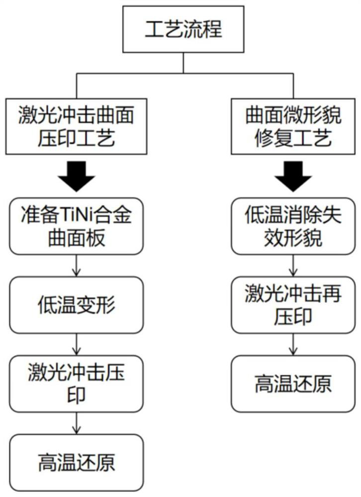
The invention belongs to the field of laser surface texture forming, and particularly relates to a laser shock curved surface embossing technology and a curved surface micro-shape repair technology. According to the laser shock curved surface embossing technology and the curved surface micro-shape repair technology, a TiNi alloy curved surface plate is pressed to form a plane plate through low-temperature deformation, then the micro-shape is made on the surface of the plane plate through the laser shock embossing technology, the plane plate is recovered to form the curved surface plate throughthe high temperature, the significant influence on the micro-shape cannot be generated in the recovery process, only the overall height of the surface micro-shape is slightly reduced, and the uniformity of the micro-shape cannot be affected. The accessory micro-shape repair technology of the laser shock curved surface embossing technology can also efficiently recover the ineffective shape of metal.

Description

technical field [0001] The invention belongs to the field of laser surface texture forming, and specifically relates to a process of laser shock curved surface embossing and curved surface micro-topography repair. The micro-topography of the alloy plate can be completely repaired without affecting the curvature of the alloy plate by the micro-topography repair process that comes with the process. Background technique [0002] As a new type of imprinting technology, laser shock imprinting has been widely used in research. This technology uses the high strain rate and high speed of the laser to create a high-precision microtopography on the metal surface without heat-affected zones, no wear marks, and no subsequent redundant processing. The process of this process is: the laser passes through the water-constrained layer (prolonging the laser action time and enlarging the laser energy peak value), the polyester black tape absorbing layer (absorbing the heat effect brought by t...

Claims


Application Information

Patent Timeline
IPC IPC(8): B23K26/356B23K26/352B23K26/60B23K26/70C22C19/03C22F3/00
CPCB23K26/356B23K26/355B23K26/60B23K26/70C22F3/00C22C19/03Y02P10/20
Inventor 程维戴峰泽
Owner JIANGSU UNIV
Learn More