A processing method of a valve seat part

A processing method and valve seat technology, which is applied in the processing field of valve seat parts, can solve the problem that the dimensional accuracy and shape and position tolerance of the valve seat parts cannot meet the overall requirements of the valve seat parts, and the cutting tools are prone to sticking, which affects the processing quality and size and other issues to achieve the effect of reducing the impact of machining accuracy, avoiding assembly errors, and improving the quality of machining

Active Publication Date: 2022-05-10
CHONGQING CHUANYI CONTROL VALVE
View PDF13 Cites 0 Cited by
  • Summary
  • Abstract
  • Description
  • Claims
  • Application Information

AI Technical Summary

Problems solved by technology

For the processing of metal base material 316L stainless steel, there are process characteristics such as large cutting heat, large linear expansion coefficient, easy to produce plastic deformation under a certain clamping force, and cutting tools are prone to sticking and easy to wear; for polytrifluoroethylene valve seat The ring base material has the characteristics of small cutting force, poor thermal conductivity and heat resistance, large thermal expansion coefficient, and the expansion coefficient of plastic is 3-4 times that of metal, and the processing chips of the polytrifluoroethylene valve seat ring are in the form of ribbons and are easy to wrap around On the cutting tool, the processing chip, the cutting tool and the part itself are squeezed against each other, thus affecting the processing quality and size
Therefore, according to the characteristics of the above-mentioned materials and the processing method, it can be known that the individual parts need to be processed separately before assembly, so the machine tool's own accessories such as three-claw, four-claw, and self-made fan-shaped clamps or slotted jackets need to be used during the processing process. Clamp the corresponding three parts separately, so that the parts will be repeatedly or repeatedly clamped during the entire processing process, and the parts are prone to deformation under the action of the clamping force, resulting in dimensional accuracy, roughness and shape. The tolerance is difficult to control, and the quality of the machined surface of the part is not controlled, and the processing and manufacturing costs are high.
[0005] In addition, after the processing of a single part is completed, although for a single part, the corresponding accuracy, size and other requirements can be achieved after each processing, but when multiple parts are assembled, due to the existence of assembly errors, it is easy to cause the final assembly The dimensional accuracy and shape tolerance of the entire valve seat parts cannot meet the overall requirements of the valve seat parts, and the judgment standard for whether the final valve seat parts meet the requirements is for the valve seat parts as a whole, not for As far as each part is concerned, the quality of the valve seat parts processed by the above method is difficult to meet the relevant requirements

Method used


Image

  • A processing method of a valve seat part
  • A processing method of a valve seat part
  • A processing method of a valve seat part

Examples


Embodiment 1

[0034] This embodiment is basically as attached Figure 1-Figure 5 shown.

[0035] A processing method for a valve seat part, characterized in that: comprising the following steps:

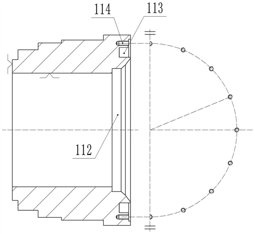
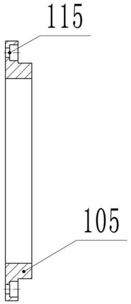
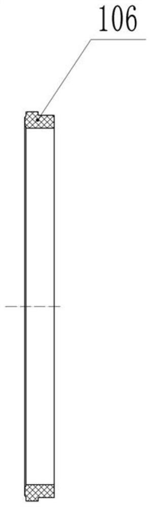
[0036] A, prepare a plurality of parts: prepare as in this embodiment figure 1 Shown valve seat support sleeve 101, figure 2 The seat guide ring 105 shown and image 3 The valve seat ring 106 shown has three parts, and the valve seat ring 106 in this embodiment is a polytrifluoroethylene valve seat ring. The outer circle of the valve seat support sleeve 101 is stepped, the left end of the valve seat support sleeve 101 is the small end, and the right end is the large end, and the right end surface of the valve seat support sleeve 101 is provided with an annular ring groove 113 and a plurality of circles evenly distributed The threaded hole 114. The valve seat guide ring 105 is annular in shape, and the outer wall of the valve seat guide ring 105 protrudes outward to form a ring-shaped connectin...

Embodiment 2

[0047] After step C, D. surface treatment of the valve seat part is also included: treating the surface of the valve seat part to make the surface roughness of the valve seat part meet the requirements.

[0048] The specific surface treatment method in this step is: Figure 6 As shown, before the surface treatment, the overall direction of the clamped workpiece is reversed, that is, the clamping part on the axial pressure plate 107 is clamped by the machine tool, and the dial indicators J01” and J02” are used to assist the clamping correction to maintain the radial direction of the clamping. , The axial precision is controlled within the specified range. Place the surface processor 116 on the tool holder of the machine tool, and place the consumables corresponding to the corresponding surface processor 116: wool wheel, white cleaning cloth wheel, and evenly soak the organic lubricant and auxiliary fine polishing agent.

[0049] During the surface treatment, the valve seat par...

Embodiment 3

[0051] It is easy to understand that in step C or step D, changes can also be made according to the actual situation, such as the determination of the clamping datum and machining datum, the moving direction of the tool, the specific structure of the clamping tool, and the parameter design in the processing process, such as When clamping the valve seat support sleeve 101, the large end of the valve seat support sleeve 101 can be used as the clamping reference for clamping, and at the same time, the valve seat pressure plate at the large end of the valve seat support sleeve 101 is clamped by a machine tool during the overall processing During the surface treatment process, the machine tool is used to clamp the valve seat pressure plate at the large end of the valve seat support sleeve 101, etc.; in step C, the tool can move from right to left, etc. All these minor changes will not affect the main invention points of this solution, and all should fall within the protection scope ...


PUM

PropertyMeasurementUnit
surface roughnessaaaaaaaaaa

Abstract

The present invention relates to the field of processing valve seat parts, in particular to a processing method for valve seat parts, comprising the following steps: A, preparing multiple parts; B, component assembly and overall clamping: assembling multiple parts into a valve seat part, Use the clamping tooling to clamp the valve seat parts axially; C. Overall processing: use the machine tool to clamp the clamping tooling, and then process the valve seat parts on the machine tool; D. Surface treatment of the valve seat parts: The surface of the seat part is treated to make the surface roughness of the seat part meet the requirements. The proposal improves the processing quality of the valve seat parts.

Description

technical field [0001] The invention relates to the field of processing valve seat parts, in particular to a processing method for valve seat parts. Background technique [0002] With the increasing use of liquefied natural gas, my country has only begun to study the structure of LNG ultra-low temperature valves in recent years. However, the manufacturing process of low-temperature key materials and components is insufficient, especially non-metallic materials and composite components, whose quality and various processes cannot meet the requirements, which often makes the manufactured valves leak beyond the standard, have a short service life, and are difficult to meet relevant domestic and foreign standards. , such as: GB / T12237-2007, API598, BS6364, ISO15848-1 or -2, SHELL77 / 306 or 77 / 312 and other standards. Among them, one of the key factors affecting valve leakage is the degree of fit between the ball core and the valve seat parts, which means the degree of sealing bet...

Claims


Application Information

Patent Timeline
Patent Type & Authority Patents(China)
IPC IPC(8): B23P15/00
CPCB23P15/001
Inventor 范贤峰蒋永兵刘兰尚洪宝李宏伟李松岭李伟
Owner CHONGQING CHUANYI CONTROL VALVE
Why Eureka
Try Eureka