
Evaporation gas recovery system of hydrogenation station

A recovery system and vaporized gas technology, applied in the field of hydrogen refueling stations, can solve the problems of single filling form, liquid hydrogen gasification, endangering public safety, etc.

Pending Publication Date: 2020-11-13
CHINA NAT OFFSHORE OIL CORP +2
View PDF0 Cites 8 Cited by
  • Summary
  • Abstract
  • Description
  • Claims
  • Application Information

AI Technical Summary

Problems solved by technology

[0003] At present, the hydrogen refueling stations built in my country mainly use high-pressure technology to store hydrogen gas sources, and the hydrogen refueling stations using high-pressure technology for hydrogen storage have defects such as low hydrogen storage capacity and single filling form. In view of the above problems, the prior art discloses a The liquid hydrogen storage and refueling station can not only refill hydrogen, but also refill high-pressure liquid hydrogen and low-pressure liquid hydrogen, which solves the above problems
Although the liquid hydrogen station has the advantage of higher storage performance, it has the problem of hydrogen gasification. The temperature of liquid hydrogen is -253°C, and its latent heat of evaporation is relatively low. Heat leakage through pipelines and storage tanks will cause liquid Hydrogen gasification, especially in the process of unloading the liquid hydrogen tanker to the liquid hydrogen storage tank in the station, will produce a large amount of hydrogen, and the hydrogen itself contains orthohydrogen and parahydrogen, which will cause the continuous evaporation of liquid hydrogen through its own reaction. In case of overpressure, it will be emptied into the atmosphere in the form of gas from the exhaust pipe like the current liquefied natural gas filling station, which will not only cause a serious waste of energy, but may even cause an explosion, endangering public safety

Method used


Image

  • Evaporation gas recovery system of hydrogenation station
  • Evaporation gas recovery system of hydrogenation station
  • Evaporation gas recovery system of hydrogenation station

Examples


Embodiment Construction

[0041] The present invention will be further described in detail below in conjunction with the accompanying drawings and embodiments. It should be understood that the specific embodiments described here are only used to explain the present invention, but not to limit the present invention. In addition, it should be noted that, for the convenience of description, only some structures related to the present invention are shown in the drawings but not all structures.

[0042] In the description of the present invention, unless otherwise clearly specified and limited, the terms "connected", "connected" and "fixed" should be understood in a broad sense, for example, it can be a fixed connection, a detachable connection, or an integrated ; It can be a mechanical connection or an electrical connection; it can be a direct connection or an indirect connection through an intermediary, and it can be the internal communication of two components or the interaction relationship between two ...


PUM


Abstract

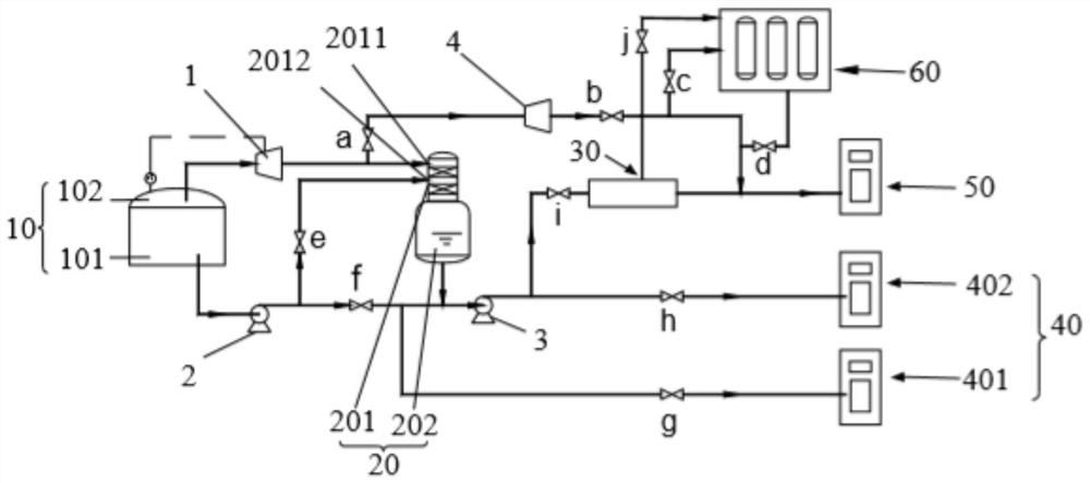
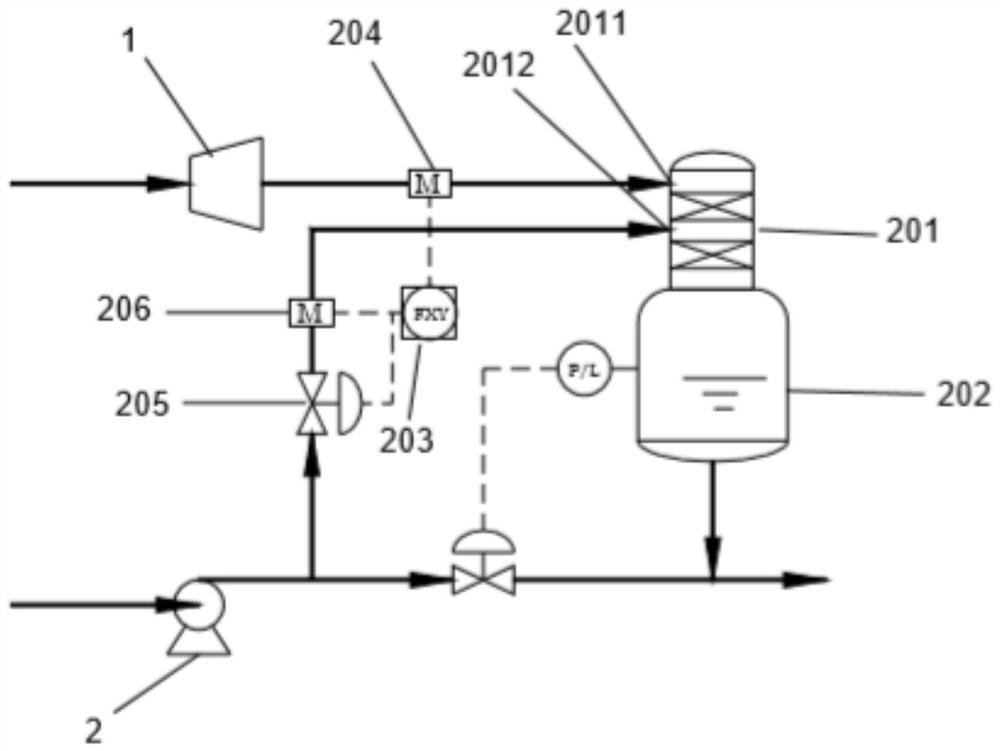
The invention relates to the technical field of hydrogenation stations, and discloses an evaporation gas recovery system of a hydrogenation station. The evaporation gas recovery system of the hydrogenation station comprises a hydrogen storage tank, a hydrogen liquefaction system, a liquid hydrogen gasification system, a liquid hydrogen filling system, a hydrogen filling system and a hydrogen buffering system, wherein the hydrogen storage tank comprises a liquid hydrogen storage space and a low-temperature gas phase space; the inlet end of the hydrogen liquefaction system respectively communicates with the liquid hydrogen storage space and the low-temperature gas phase space; the outlet end of the hydrogen liquefaction system respectively communicates with the liquid hydrogen filling systemand the liquid hydrogen gasification system; the outlet end of the liquid hydrogen gasification system communicates with the hydrogen filling system; the hydrogen filling system communicates with thelow-temperature gas phase space; the hydrogen buffering system is connected in parallel on a pipeline communicating the hydrogen filling system with the low-temperature gas phase space; and the hydrogen buffering system communicates with the liquid hydrogen gasification system. The evaporation gas recovery system of the hydrogenation station can achieve mixed filling, and can fully recycle hydrogen evaporation gas in the station to achieve energy conservation and emission reduction.

Description

technical field [0001] The invention relates to the technical field of hydrogen refueling stations, in particular to an evaporation gas recovery system of a hydrogen refueling station. Background technique [0002] Hydrogen energy is recognized as clean energy, and the calorific value of hydrogen is the highest among common fuels, about 3 times that of petroleum and 4.5 times that of coal. Therefore, hydrogen energy vehicles can reduce air pollution, reduce greenhouse gas emissions and lower the impact on traditional energy It has outstanding advantages in terms of dependence and other aspects, among which, the hydrogen refueling station facilities that provide hydrogen energy for hydrogen fuel cell vehicles will be very critical. [0003] At present, the hydrogen refueling stations built in my country mainly use high-pressure technology to store hydrogen gas sources, and the hydrogen refueling stations using high-pressure technology for hydrogen storage have defects such as...

Claims


Application Information

Patent Timeline
IPC IPC(8): F17C5/02F17C7/04F17C13/00F17C13/02
CPCF17C5/02F17C7/04F17C13/00F17C13/026F17C2201/0119F17C2201/032F17C2201/052F17C2221/012F17C2223/0153F17C2223/035F17C2225/0123F17C2225/0153F17C2227/039F17C2265/063Y02E60/32Y02P90/45
Inventor 曲顺利王江涛鹿晓斌张京周贺同强郭雷赵彩云
Owner CHINA NAT OFFSHORE OIL CORP
Learn More