Metal pipe fitting port polishing device
A technology for metal pipe fittings and ports is applied in the field of metal pipe fitting port grinding devices, which can solve the problems of inconvenient clamping, laborious grinding, and a lot of metal dust, so as to achieve the effects of convenient movement and parking, reducing dust hazards and improving stability.
- Summary
- Abstract
- Description
- Claims
- Application Information
AI Technical Summary
Problems solved by technology
Method used
Image
Examples
Embodiment
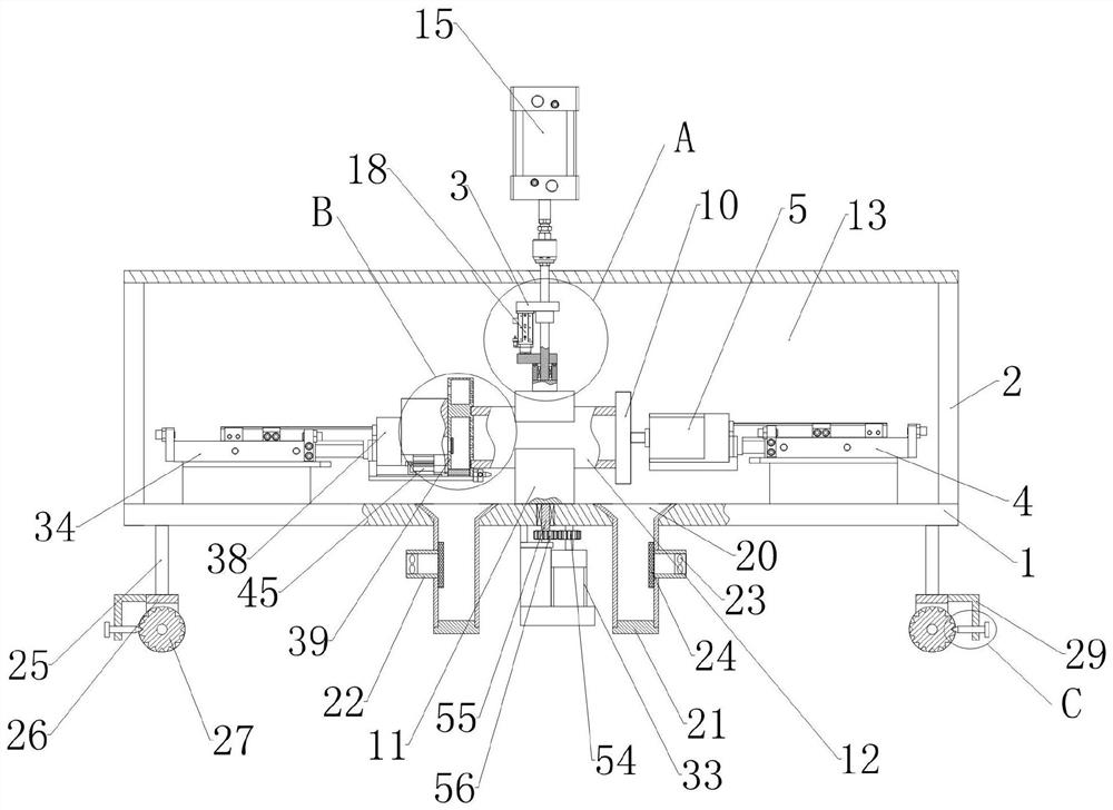
[0054] see Figure 1-11 , a metal pipe fitting port grinding device, including a support table 1;
[0055] The supporting base driving device is installed on the supporting base 1, the output end of the supporting base driving device is connected with the supporting base 11, and the supporting base driving device acts on the supporting base 11, so that: the supporting base 11 can rotate relative to the supporting base 1, and the supporting base The top end of 11 has a supporting seat clamping groove 36;
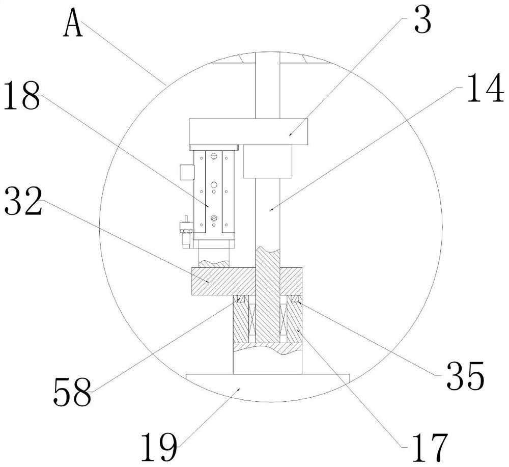
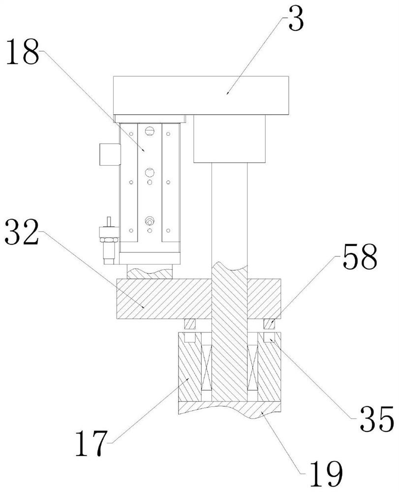
[0056] The upper end of the support table 1 is fixedly connected with a support frame 2, and the upper end of the support frame 2 is fixedly connected with a support plate 13, and the support plate 13 is equipped with a deck driving device 15, and the output end of the deck driving device 15 The deck connecting rod 14 is connected, and the deck driving device 15 acts on the deck connecting rod 14, so that: the deck connecting rod 14 can move up and down relative to the suppo...
Embodiment 2
[0066] This embodiment makes the following further limitations on the basis of Embodiment 1: the abutment plate 39 has a hollow dust collection chamber 40, and the inner side of the abutment plate 39 is provided with several dust suction chambers communicating with the dust collection chamber 40. hole 41;
[0067] The outer end of the abutment plate 39 is provided with an air exhaust hole 42 communicating with the dust collection chamber 40, and the air exhaust hole 42 is provided with an abutment plate filter 43;
[0068] The bottom end of the abutment plate 39 is provided with a release port 44, and a baffle drive device 45 is installed on the abutment plate connection frame 38, and the output end of the baffle drive device 45 is connected with an abutment plate baffle that can close the release port 44. plate 46.
[0069] In this embodiment, the baffle driving device 45 can be a small air cylinder or an electric push rod. The exhaust hole 42 communicates with an exhaust f...
Embodiment 3
[0077] This embodiment makes the following further limitations on the basis of Embodiment 1: the front and rear side walls of the support seat clamping groove 36 are all set on slopes, and the groove bottom of the support seat clamping groove 36 is provided with several intervals. Support seat elastic piece 51;
[0078] The front and rear sidewalls of the card holder holding groove 37 are all inclined, and the groove bottom of the card holder holding groove 37 is provided with several card holder elastic pieces 52 arranged at intervals.
[0079] In this embodiment, the support seat elastic piece 51 should be arranged in the support seat clamping groove 36 along the axial direction of the metal pipe, and several support seat elastic pieces 51 are arranged in the support seat clamping groove 36 forward and backward. The card seat elastic piece 52 should be arranged in the card seat clamping groove 37 along the axial direction of the metal pipe, and several card seat elastic plat...
PUM
 Abstract
Description
Claims
Application Information
 - R&D Engineer
- R&D Manager
- IP Professional
- Industry Leading Data Capabilities
- Powerful AI technology
- Patent DNA Extraction
Browse by: Latest US Patents, China's latest patents, Technical Efficacy Thesaurus, Application Domain, Technology Topic, Popular Technical Reports.
© 2024 PatSnap. All rights reserved.Legal|Privacy policy|Modern Slavery Act Transparency Statement|Sitemap|About US| Contact US: help@patsnap.com


