Device for improving stable operation of liquid crystal equipment
A technology for stable work and equipment, applied in the direction of instruments, static indicators, etc., can solve the problems of integrated circuit damage, economic loss, etc., and achieve the effects of ensuring safety, ensuring stable work, and protecting from being burned
- Summary
- Abstract
- Description
- Claims
- Application Information
AI Technical Summary
Problems solved by technology
Method used
Image
Examples
Embodiment 1
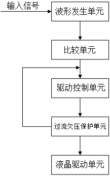
[0033] Such as figure 1 As shown, the device for improving the stable operation of liquid crystal devices proposed by the present invention includes a waveform generating unit, a comparison unit, a drive control unit, an overcurrent and undervoltage protection unit, and a liquid crystal drive unit that are electrically connected in sequence, and the waveform generation unit, comparison unit, and drive control unit The units are respectively connected to the working level VIN, and the output end of the liquid crystal drive unit is connected to the liquid crystal panel unit.
[0034] The waveform generation unit receives the external input level signal VIN and generates a waveform signal of a certain frequency required by the comparison unit according to the input signal. Such as Figure 4 As shown, the waveform generating unit includes a connected hysteresis comparator and a resistance-capacitance network. The resistance-capacitance network includes resistors RK1, RK2, RK3, RK...
Embodiment 2
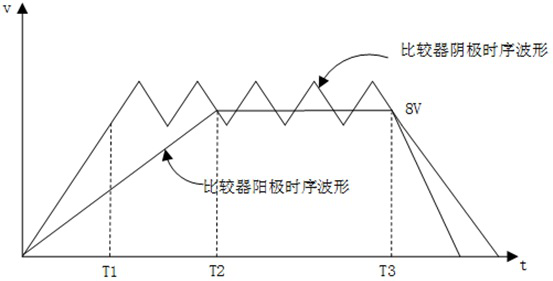
[0041] Such as image 3 Shown is the working sequence requirement of the device during the whole system power-on and off process. During the power-on and power-off process of the system, the anode terminal voltage of the comparator must be lower than the cathode terminal voltage to achieve stable and reliable operation of the system; Unable to work stably.
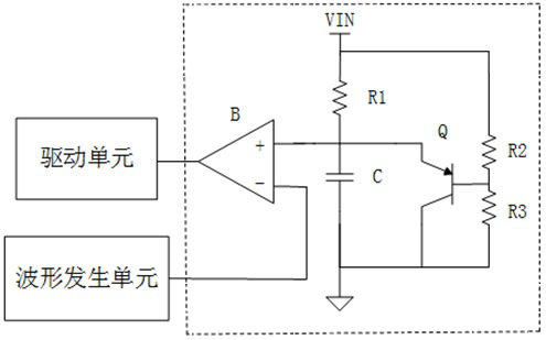
[0042] Specifically, during the power-on process of the system, the rate of voltage rise on the capacitor C is controlled by controlling the resistance value of the resistor R2 and the capacitance value of the capacitor C to ensure the voltage at the anode terminal of the transistor Q (that is, the voltage on the capacitor C) Rate of change of voltage below the cathode terminal (i.e. triangular wave voltage). In this embodiment, when Vb=7.3V is set, when the system is powered on, the time for the triangular wave to be established is T1=20ms, and it is necessary to ensure the time for the voltage of Ve to rise to 8v, that...
PUM
 Abstract
Description
Claims
Application Information
 - R&D
- Intellectual Property
- Life Sciences
- Materials
- Tech Scout
- Unparalleled Data Quality
- Higher Quality Content
- 60% Fewer Hallucinations
Browse by: Latest US Patents, China's latest patents, Technical Efficacy Thesaurus, Application Domain, Technology Topic, Popular Technical Reports.
© 2025 PatSnap. All rights reserved.Legal|Privacy policy|Modern Slavery Act Transparency Statement|Sitemap|About US| Contact US: help@patsnap.com


