
Novel melt-blown non-woven fabric and manufacturing method and production equipment thereof

A technology of meltblown nonwovens and production equipment, which is applied in nonwovens, rayon manufacturing, melt spinning, etc.

Pending Publication Date: 2020-10-23
NANJING BAIMEI PLASTIC
View PDF2 Cites 4 Cited by
  • Summary
  • Abstract
  • Description
  • Claims
  • Application Information

AI Technical Summary

Problems solved by technology

[0008] Technical purpose: Aiming at the deficiencies of existing melt-blown nonwoven fabrics, the present invention discloses a new type of melt-blown nonwoven fabric with simple manufacturing process, good melt flow rate, uniform flow velocity distribution, and high melt-blown pressure and its manufacturing method and production equipment

Method used

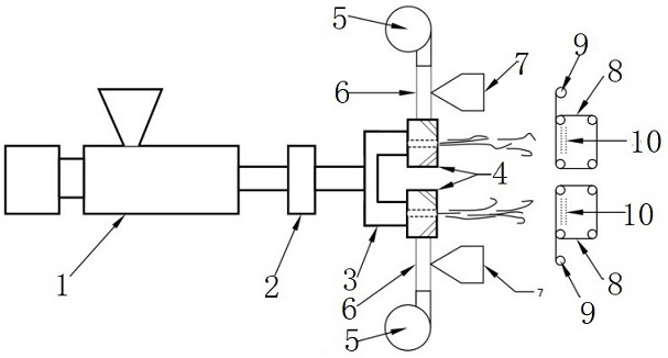

Image

  • Novel melt-blown non-woven fabric and manufacturing method and production equipment thereof
  • Novel melt-blown non-woven fabric and manufacturing method and production equipment thereof

Examples


Embodiment 1

[0047] S01. Use silicon dioxide as the functional particle, and dry it in a vacuum oven at 80°C for 12 hours in advance. Weigh 100 parts of silicon dioxide particles, 1 part of polyethylene wax dispersant, and 1 part of The KH550 coupling agent was added into an ultrasonic reactor with an ultrasonic frequency of 25khz, subjected to ultrasonic modification for 30min, and then taken out and dried at a drying temperature of 80°C and a drying time of 10 h to obtain the modified silica particles ;

[0048] S02. Pre-dry the polypropylene resin particles in a vacuum drying oven at 80°C for 12 hours, and then weigh 99% of the polypropylene resin particles and 1% of the modified silica functional particles according to the mass fraction and add them to a rotating speed of 1500~ Mix in a mixer at 2000r / min, put the compound into the hopper of the twin-screw extruder (1), and melt it in the screw extruder (1);

[0049] S03. After being filtered by the filter device (2), it is diverted b...

Embodiment 2

[0052] The difference with embodiment 1 is:

[0053] 1. Add 100 parts of activated carbon particles, 4 parts of OP-10 dispersant, and 6 parts of KH560 coupling agent into the ultrasonic reactor with an ultrasonic frequency of 25khz according to the mass fraction of the modified functional particles, carry out ultrasonic modification for 50min, and then take it out drying, the drying temperature is 80°C, and the drying time is 8 h, to obtain the modified activated carbon particles;

[0054] 2. Polylactic acid particles are used as resin particles, and 94% polylactic acid resin particles and 6% modified activated carbon particles are used as raw materials according to the mass fraction.

Embodiment 3

[0056] The difference with embodiment 1 is:

[0057] 1. Add 100 parts of zeolite particles, 2 parts of OP-10 dispersant and 4 parts of KH560 coupling agent into the ultrasonic reactor with ultrasonic frequency of 25khz according to the mass fraction of modified functional particles, carry out ultrasonic modification for 50min, and then take out drying, the drying temperature is 80°C, and the drying time is 6 h, to obtain the modified zeolite particles;

[0058] 2. Polylactic acid particles are used as resin particles, and 96% polylactic acid resin particles and 4% modified zeolite particles are used as raw materials according to the mass fraction.


PUM

PropertyMeasurementUnit
Breaking strengthaaaaaaaaaa

Abstract

The invention discloses a novel melt-blown non-woven fabric as well as a manufacturing method and production equipment thereof. The novel melt-blown non-woven fabric comprises the following raw materials in%age by mass: 94-99% of resin particles and 1-6% of modified functional particles, wherein the modified functional particles are prepared from the following components in%age by mass: 100 partsof functional particles, 1-4% of dispersing agent and 1-6% of coupling agent; fully drying and mixing the modified functional particles and the resin particles, melting, filtering, shunting and extruding, stretching and spraying under high-speed air flow, adhering to the surface of a receiving device in the presence of negative pressure, and then cooling and forming; the novel melt-blown non-wovenfabric is high in breaking strength and good in sterilization effect, and the manufacturing method has the advantages of being simple in process, good in melt flow rate, uniform in flow velocity distribution, large in melt-blown pressure and the like.

Description

technical field [0001] The invention relates to the technical field of textile nonwovens, in particular to a novel melt-blown nonwoven fabric and its manufacturing method and production equipment. Background technique [0002] Meltblown nonwovens are a kind of polymer spun-laid nonwovens, which originated in the early 1900s. At that time, the U.S. Naval Laboratory developed a filter material with ultra-fine filtration effect in order to collect radioactive particles in the upper atmosphere with government funding. This method is the prototype of modern melt-blown nonwoven technology. In the mid-1990s, the company also began to conduct research on melt-blown nonwovens technology and obtained a series of patents. [0003] The principle of the melt blown process is to extrude the polymer melt from the spinneret hole of the die head to form a thin flow of melt, and the heated stretching air is blown out at high speed from the air ducts on both sides of the spinneret hole of th...

Claims


Application Information

Patent Timeline
IPC IPC(8): D04H1/56D04H1/544D04H1/55D01D4/06D01D5/098D01F6/46D01F6/92D01F1/10D06M10/00D06M101/20D06M101/32
CPCD01D4/06D01D5/0985D01F1/10D01F6/46D01F6/92D04H1/544D04H1/55D04H1/56D06M10/00D06M16/00D06M2101/20D06M2101/32
Inventor 杨小燕杨福兴杨桂明伍凯飞苏建华
Owner NANJING BAIMEI PLASTIC
Learn More