
NiAl alloy complicated thin-wall hollow component shaping method

An alloy and complex technology, applied in the field of forming NiAl alloy complex thin-walled hollow components, can solve the problems of material performance difference, difficult deformation and high production cost in the area near the weld

Active Publication Date: 2020-10-23
HARBIN INST OF TECH
View PDF10 Cites 7 Cited by
  • Summary
  • Abstract
  • Description
  • Claims
  • Application Information

AI Technical Summary

Problems solved by technology

However, NiAl alloy is difficult to deform, high production cost, and long cycle; for complex thin-walled hollow components, the forming difficulty is particularly prominent, and the forming accuracy and microstructure and performance control are difficult
[0004] The invention patent with the publication number CN110142332A provides an integrated method for the forming and control of NiAl alloy thin-walled pipe fittings. There are still some technical problems to be solved in the preparation and forming of thin-walled hollow components
This is mainly reflected in: (1) The deformed Ni foil raw material is not heat-treated, which reduces the uniformity and coordination of the deformation of the Ni / Al laminated foil, thereby reducing the formability of the component
(2) The welding method is used to process the butt joints of Ni / Al laminated foil tubes, which will reduce the safety and reliability of use; in addition, the alloy composition in the local area of ​​the weld may deviate from the composition requirements of the NiAl single-phase region, resulting in the area near the weld The difference in material properties increases the possibility of instability at the weld

Method used

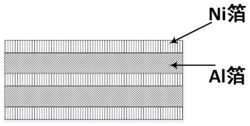

Image

  • NiAl alloy complicated thin-wall hollow component shaping method
  • NiAl alloy complicated thin-wall hollow component shaping method
  • NiAl alloy complicated thin-wall hollow component shaping method

Examples


Embodiment 1

[0076] A preparation and forming method of a NiAl alloy complex thin-walled hollow component, the structure of the complex thin-walled hollow component is as follows Figure 4 shown. Its main characteristics are as follows: (i) the shape is complex, the section at one end is circular, the section at the other end is rectangular, and there is a linear transition in the length direction, that is, the shape of the section changes greatly; (ii) the perimeter of the section varies greatly, and the perimeter of the rectangular section is 2.0 times the circumference of the circular section; (iii) the wall thickness is small, and the wall thickness ranges from 1.0 to 2.5mm, that is, the rigidity is weak and the dimensional accuracy is difficult to control; (iv) the wall thickness uniformity is high, and the wall thickness tolerance is ±0.2mm; (v) High temperature performance and high safety and reliability requirements. The above characteristics show that it is extremely difficult to...


PUM

PropertyMeasurementUnit
Strain rateaaaaaaaaaa

Abstract

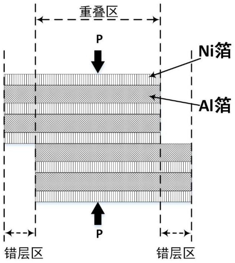
The invention relates to the technical field of hollow component shaping, in particular to a NiAl alloy complicated thin-wall hollow component shaping method. According to the NiAl alloy complicated thin-wall hollow component shaping method, heat treatment of Ni foil is conducted, dislocation and other defect density of the Ni foil can be lowered, the yield strength of the Ni foil is lowered, theelongation of the Ni foil is improved, and harmonious deformation evenness of laminated raw materials is optimized, so a complicated thin-wall hollow component with even wall thickness and excellent performance can be conveniently obtained. An overlapping zone of a first laminated foil is pressed before shaping, an overlapping zone laminated foil based on spreading metallurgical bonding can be formed between the Ni foil and Al foil in the overlapping zone, so the deformation is more even and harmony in a following shaped complicated thin-wall hollow component, displacement or delamination arenot easily caused, and the shaping performance is better. The complicated thin-wall hollow component is prepared in the manner of staggered overlap joint, welding is not required, consistency in constitution of overlap joint seams and other parts of the component can be ensured, the use safety and reliability are higher, the wall thickness evenness is better and the precision of the component is higher.

Description

technical field [0001] The invention relates to the technical field of hollow member forming, in particular to a method for forming a NiAl alloy complex thin-walled hollow member. Background technique [0002] In industrial fields such as national defense equipment, hollow thin-walled components with closed cross-sections are widely used, such as isolation sections, air inlets, nozzles, and outlet pipes of high-speed aircraft. Since the service temperature is as high as 800 °C or more, such components often need to be made of high-temperature resistant materials. At present, the widely used high-temperature-resistant alloy material is Ni-based superalloy. [0003] In recent years, with the further increase of aircraft flight speed, the operating temperature of key components has also increased significantly, and the operating temperature of key components of a new generation of high-speed aircraft has reached the limit of the operating temperature of superalloys. In additio...

Claims


Application Information

Patent Timeline
IPC IPC(8): B21D33/00B21D37/16C22F1/02C22F1/10C22F1/04C21D9/46B23P23/00
CPCB21D33/00B21D37/16C22F1/02C22F1/10C22F1/04C21D9/46B23P23/00
Inventor 王东君刘钢苑世剑
Owner HARBIN INST OF TECH
Learn More