
Anti-deformation pipe fitting fixing device for machining

A technology of machining and fixing devices, applied in workpiece clamping devices, positioning devices, metal processing machinery parts, etc., can solve problems such as pipe deformation, improve anti-skid performance, ensure fixing effect, and improve the effect of fixing effect.

Inactive Publication Date: 2020-09-29
高彦科
View PDF6 Cites 9 Cited by
  • Summary
  • Abstract
  • Description
  • Claims
  • Application Information

AI Technical Summary

Problems solved by technology

[0004] Most of the fixing designs based on traditional pipe fittings processing are relatively simple. Generally, external extrusion on both sides is used for fixing. When targeting thinner wall thickness pipe fittings, it is easy to cause the technical problem of pipe deformation. This invention proposes a kind of anti-deformation for machining Pipe Fixtures

Method used


Image

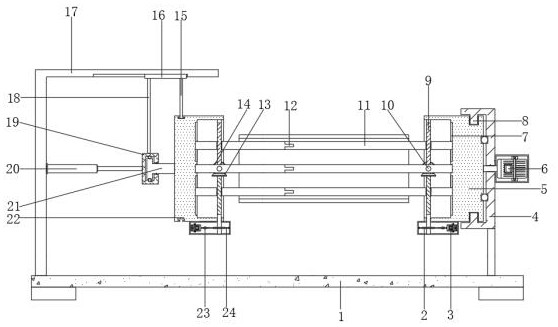
  • Anti-deformation pipe fitting fixing device for machining
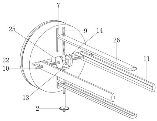
  • Anti-deformation pipe fitting fixing device for machining
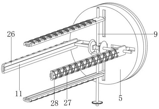
  • Anti-deformation pipe fitting fixing device for machining

Examples


Embodiment 1

[0030] refer to Figure 1-4 , an anti-deformation pipe fixing device for mechanical processing, comprising a base 1, and brackets and L-shaped fixed vertical plates 17 are respectively welded on both sides of the top outer wall of the base 1, and one side of the L-shaped fixed vertical plate 17 is fixed with hydraulic pressure by bolts. Rod 20, a clamping mechanism is installed on the top of the base 1, and the clamping mechanism includes a fixed installation end 5 and a movable installation end 22, the fixed installation end 5 and the movable installation end 22 are both cylindrical, and the fixed installation end 5 and the movable installation The inner bottom of the end 22 is provided with four evenly distributed limiting chute 7, the inner wall of the limiting chute 7 is slidingly connected with the moving rod 11, and the outer wall of one side of the moving rod 11 is welded with an arc-shaped stop plate 26 , the outer wall of the arc-shaped backing plate 26 is fixedly ins...

Embodiment 2

[0041] refer to Figure 5 , an anti-deformation pipe fixing device for mechanical processing. Compared with Embodiment 1, this embodiment also includes that the bottom outer wall of the moving rod 11 is welded with extension blocks distributed equidistantly, and both sides of one end of the extension block are connected by hinges. Arm bar 29 is arranged, and one end of arm bar 29 is all welded with hemispherical block 31, and the outer wall of hemispheric barn 31 is all bonded with the bar edge 32 of equidistant distribution, and the opposite side of extension block and arm bar 29 is all welded with Tension spring 30.

[0042] When the present invention is used, while the arc-shaped support plate 26 supports the pipe fitting, the tension spring 30 can be used to pull the arm bar 29 to approach the corresponding moving rod 11, and then pull the hemispherical block 31 and the strip edge 31 against the inner wall of the pipe fitting. Thereby, the purpose of further improving the...


PUM


Abstract

The invention belongs to the technical field of machining, and particularly relates to an anti-deformation pipe fitting fixing device for machining. Aiming at the problem that most traditional fixingdesigns for pipe fitting machining are simple, generally, fixing is conducted by adopting the mode of extruding the exteriors of two sides, and thin-wall pipe fittings are prone to being deformed, thefollowing scheme is provided, the anti-deformation pipe fitting fixing device comprises a base, and a bracket and an L-shaped fixing vertical plate are welded to the two sides of the outer wall of the top of the base correspondingly; and a hydraulic rod is fixed to one side of the L-shaped fixing vertical plate through a bolt, and a clamping mechanism is installed at the top end of the base. According to the anti-deformation pipe fitting fixing device, driving bi-directional screws can be driven to rotate by arranging a driving mechanism, in the meantime, corresponding driven screws are driven to rotate oppositely through driving conical teeth and driven conical teeth which are the same in specification, accordingly, moving rods on limiting slide groove operate away from each other at thesame time and expand outwards, and uniform supporting and fixing treatment on the inner wall of a pipe fitting are achieved through arc-shaped abutting plates.

Description

technical field [0001] The invention relates to the technical field of mechanical processing, in particular to an anti-deformation pipe fixing device for mechanical processing. Background technique [0002] Machinery is a combination of man-made physical components. There is a definite relative motion between the various parts of the machine. In addition to the characteristics of the mechanism, the machine must also have the third characteristic, that is, the mechanism that can replace human labor to complete useful mechanical work or convert mechanical energy, so the machine can convert mechanical energy or complete useful mechanical work. Machining refers to the process of changing the shape or performance of a workpiece through a mechanical device. According to the difference in processing method, it can be divided into cutting processing and pressure processing. [0003] Pipe fittings are widely used in the mechanical field, and they need to be fixed during processing...

Claims


Application Information

Patent Timeline
IPC IPC(8): B23Q3/06B25B11/00
CPCB23Q3/065B25B11/00
Inventor 高彦科
Owner 高彦科
Learn More