
Supporting device for high-accuracy adjustable optical elements

An optical element and supporting device technology, applied in optical elements, optics, installation, etc., can solve the problems of inability to effectively overcome the self-weight deformation of optical elements, the accuracy is difficult to meet the requirements of high-precision surface shape, and it does not have the ability to actively deform. Reliable supporting state of components, improving the effect of adjusting the displacement transmission ratio and overcoming deformation

Inactive Publication Date: 2015-02-18
CHANGCHUN INST OF OPTICS FINE MECHANICS & PHYSICS CHINESE ACAD OF SCI
View PDF8 Cites 14 Cited by
  • Summary
  • Abstract
  • Description
  • Claims
  • Application Information

AI Technical Summary

Problems solved by technology

[0003] The commonly used supporting devices for optical components cannot effectively overcome the self-weight deformation of optical components, and their precision is difficult to meet the requirements of high-precision surface shape. Therefore, it is necessary to design a special support device to overcome the self-weight deformation of optical components. Compensating the wave aberration of the optical system
Currently publicly available support devices for optical components such as CN201110212311.0, CN201210510940.6, CN201310322942.7, etc., these support devices require high consistency of each key component, that is, the requirements for machining accuracy are too harsh, which greatly increases the difficulty of processing , and does not have the ability to actively deform

Method used


Image

  • Supporting device for high-accuracy adjustable optical elements
  • Supporting device for high-accuracy adjustable optical elements
  • Supporting device for high-accuracy adjustable optical elements

Examples


Embodiment Construction

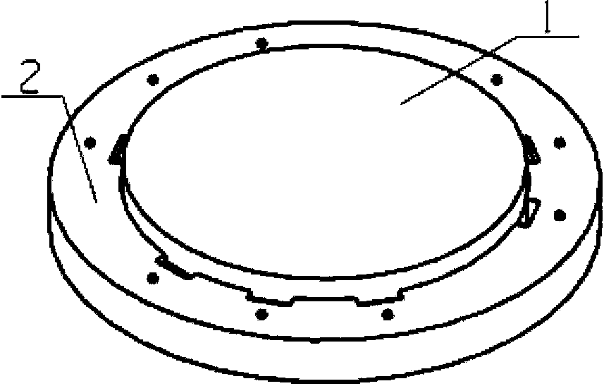
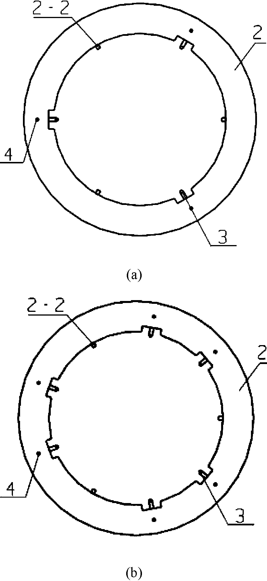
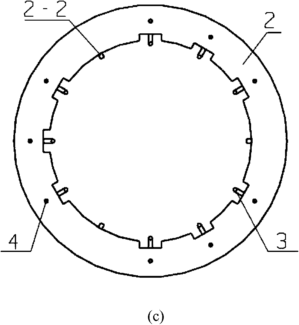
[0020] The inventive idea of ​​the present invention is: a high-precision adjustable optical element support device, which includes: a mirror frame with three-point fixed support, adjustable flexible auxiliary support shrapnel, multi-stage displacement reduction flexible hinge, thread adjustment rod, thread lock Springs, screws.

[0021] The picture frame is the ring-shaped main structure of the support device, which has good rigidity and is generally made of stainless steel or Invar. Adjusting rod and threaded locking spring mounting threaded hole;

[0022] The three-point fixed support is evenly distributed in the circumferential direction of 120°, and its support surface can be designed as a slope tangent to the optical element or a radius of curvature slightly larger than the spherical surface of the optical element, which is convenient for fixing the optical element and the frame with structural glue;

[0023] The number of the adjustable flexible auxiliary support shrap...


PUM


Abstract

The invention relates to a supporting device for high-accuracy adjustable optical elements and belongs to the technical field of manufacturing, mounting and adjusting of high-accuracy optical elements. The supporting device comprises a mirror frame with a three-point fixed support, adjustable flexible auxiliary supporting elastic pieces, multistage displacement contraction flexible hinges, threaded adjusting rods, threaded locking springs and screws, the three-point fixed support is used for bonding of the optical elements, the adjustable flexible auxiliary supporting elastic pieces play a role in auxiliary supporting of the optical elements, and the multistage displacement contraction flexible hinges, the threaded adjusting rods and the threaded locking springs form a high-resolution displacement adjusting mechanism to adjust positions of the adjustable flexible auxiliary supporting elastic pieces. The supporting device can be widely applied to refractive, reflective, planar, spherical and aspheric optical elements, harsh requirements, on processing accuracy, of the high-accuracy supporting device can be lowered effectively, uniform supporting force and nonuniform supporting force are provided to the optical elements accurately, and deformation caused by dead weight of the optical elements is avoided effectively while the supporting device has active deformation capability.

Description

technical field [0001] The invention relates to the technical field of high-precision optical element manufacturing and assembly, in particular to a support device for high-precision adjustable optical elements. Background technique [0002] With the development of modern optical design and manufacturing, higher and higher requirements are put forward for the surface precision of optical components, especially in the field of deep ultraviolet and extreme ultraviolet lithography optics, optical components are required to ensure surface precision RMS value in nanometers even down to the sub-nanometer level. [0003] The commonly used supporting devices for optical components cannot effectively overcome the self-weight deformation of optical components, and their precision is difficult to meet the requirements of high-precision surface shape. Therefore, it is necessary to design a special support device to overcome the self-weight deformation of optical components. Compensate ...

Claims


Application Information

Patent Timeline
IPC IPC(8): G02B7/00
CPCG02B7/00
Inventor 吴志会王东平倪明阳李显凌杨怀江隋永新
Owner CHANGCHUN INST OF OPTICS FINE MECHANICS & PHYSICS CHINESE ACAD OF SCI
Learn More