Eureka AIR delivers breakthrough ideas for toughest innovation challenges, trusted by R&D personnel around the world.

Power plant denitration ammonia injection control system

A technology for control systems and power plants, applied in the direction of electric controllers, comprehensive factory control, controllers with specific characteristics, etc., can solve problems such as difficulty in quickly responding to changes in NOX concentration at the inlet, and no effect has been achieved, so as to prevent output shocks, Effects of improving response speed and eliminating static deviation

Active Publication Date: 2020-09-11
DATANG LUBEI POWER GENERATION
View PDF7 Cites 4 Cited by
  • Summary
  • Abstract
  • Description
  • Claims
  • Application Information

AI Technical Summary

Problems solved by technology

Since the chemiluminescence dilution method is used to measure the NOX concentration at the outlet and inlet of the reactor, there is a delay in the measurement system itself, so it is difficult to quickly respond to the change of the NOX concentration at the inlet;
[0007] (3) The reaction efficiency is relatively stable. Due to the stable reaction environment and catalyst activity, the linearity of the relationship between the amount of ammonia injection and the difference in the concentration of NOx at the outlet and inlet of the reactor is observed through the curve; after analysis, the original control method was adopted to increase Methods such as dynamic differential feedforward of NOX concentration at the reactor inlet, denitrification efficiency feedforward, load change feedforward and modification of PID parameters have not achieved ideal results.

Method used


Image

  • Power plant denitration ammonia injection control system
  • Power plant denitration ammonia injection control system
  • Power plant denitration ammonia injection control system

Examples


Embodiment Construction

[0024] The present invention will be described in detail below in conjunction with the accompanying drawings. It should be noted in advance that the upper, lower, left, and right orientation words in this application are consistent with the upper, lower, left, and right orientation words in the drawings of the specification, but are not limited to the orientation of specific structures.

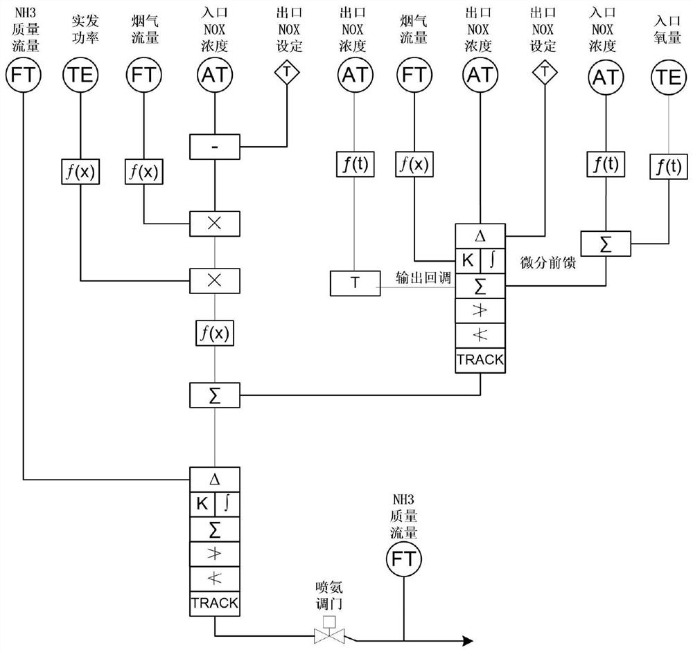
[0025] A control system for denitrification and ammonia injection in a power plant, which adopts a cascade control system to improve the response speed of inlet NOX concentration disturbances, such as figure 1 As shown, the cascade control system includes: dynamic differential feedforward of NOX concentration at the reactor inlet, feedforward of denitrification efficiency, load change feedforward, PID modification parameters, and control process of outlet NOX deviation correction. The control logic of outlet NOX deviation correction includes The following steps:

[0026] Step 1 Calculate the...


PUM


Abstract

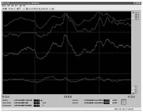
The invention discloses a power plant denitration ammonia injection control system, wherein a cascade control system is adopted to improve the response speed of inlet NOX concentration disturbance andcomprises: a dynamic differential feedforward of reactor inlet NOX concentration, a denitration efficiency feedforward, a load change feedforward, PID modification parameters and a control process ofoutlet NOX deviation correction, and the denitration ammonia injection control system adopts a waveform judgment method for callback. The judgment logic of the waveform judgment method is as follows:when the outlet NOX concentration curve has a sinusoidal oscillation waveform, the ammonia injection amount is quickly called back in the second quarter period of the sinusoidal oscillation waveform.According to the cascade control system for calculating the NH3 demand quantity according to NOX at the inlet of the SCR reaction zone, the ammonia spraying response speed is increased; outlet NOx deviation correction is added in a control algorithm, so that static deviation is eliminated; and meanwhile, a waveform judgment method is adopted for callback, so that the phenomenon of output oscillation is prevented, and thereby, the problems of response lag of inlet NOx concentration disturbance and output oscillation are solved.

Description

technical field [0001] The invention relates to the technical field of electric power thermal control, and specifically refers to a control system for denitrification and ammonia injection in a power plant. Background technique [0002] Thermal power generation is the main force in the development of electric power in modern society. It uses combustible materials (such as coal) to generate electricity. Although there are some nuclear power units in China, thermal power still occupies most of the electricity market. [0003] At present, most of the flue gas denitrification in thermal power plants adopts the selective catalytic reduction (SCR) method. During the operation process, the outlet NOX concentration discharges instantaneously exceeds the standard or the ammonia escapes excessively, which leads to the blockage of the air preheater with ammonium bisulfate. The SCR denitrification ammonia injection system adopts a single-loop closed-loop control method for the deviation...

Claims


Application Information

Patent Timeline
IPC IPC(8): B01D53/86B01D53/56G05B11/42
CPCB01D53/8696B01D53/8625G05B11/42B01D2251/2062Y02P90/02
Inventor 付俊杰赵进
Owner DATANG LUBEI POWER GENERATION
Why Eureka
Eureka Blog
Learn More