
Model predictive control apparatus

a control apparatus and model technology, applied in adaptive control, instruments, digital computer details, etc., can solve the problems of delayed response to a fast change in the situation, adverse effects of prediction accuracy on the control performance, and adverse effects of numerical condition of the control computation

Inactive Publication Date: 2008-08-26
NISSAN MOTOR CO LTD
View PDF9 Cites 148 Cited by
  • Summary
  • Abstract
  • Description
  • Claims
  • Application Information

AI Technical Summary

Benefits of technology

The present invention provides a model predictive control apparatus that can quickly respond to changes in environmental situations. It uses a system behavior prediction section to predict the future state of the system, and an objective function reference section to provide a normal value of the objective function. An initial solution generation section sets the initial function definition data and generates the initial optimal value of the control input. An optimization section calculates the optimal value of the control input correction over the control horizon and outputs the optimal value of the control input. The apparatus can control the system in real-time and improve its performance.

Problems solved by technology

In a model predictive control method, its prediction inaccuracy adversely affects its control performance, because the current value of a control input to a system is determined in accordance with a predicted value of future time series system state as mentioned above.
In some model predictive control systems, however, it is possible that the control input is desired to largely change from the immediately preceding control input, for some reasons, for example, for reasons of an increase in prediction inaccuracy.
In such a situation, it is possible that the numerical condition of the control computation varies adversely.
However, this operation also tends to reduce the control input change so that it is possible that the response to a fast change in the situation is delayed.
In a case the model predictive control is applied to a driver support apparatus of an automotive vehicle, it is possible that its delayed response to the situation change has a significant problem.
In that situation, it is possible that the response of the above-mentioned method of improving the numerical condition is delayed.

Method used


Image

  • Model predictive control apparatus
  • Model predictive control apparatus
  • Model predictive control apparatus

Examples


first embodiment

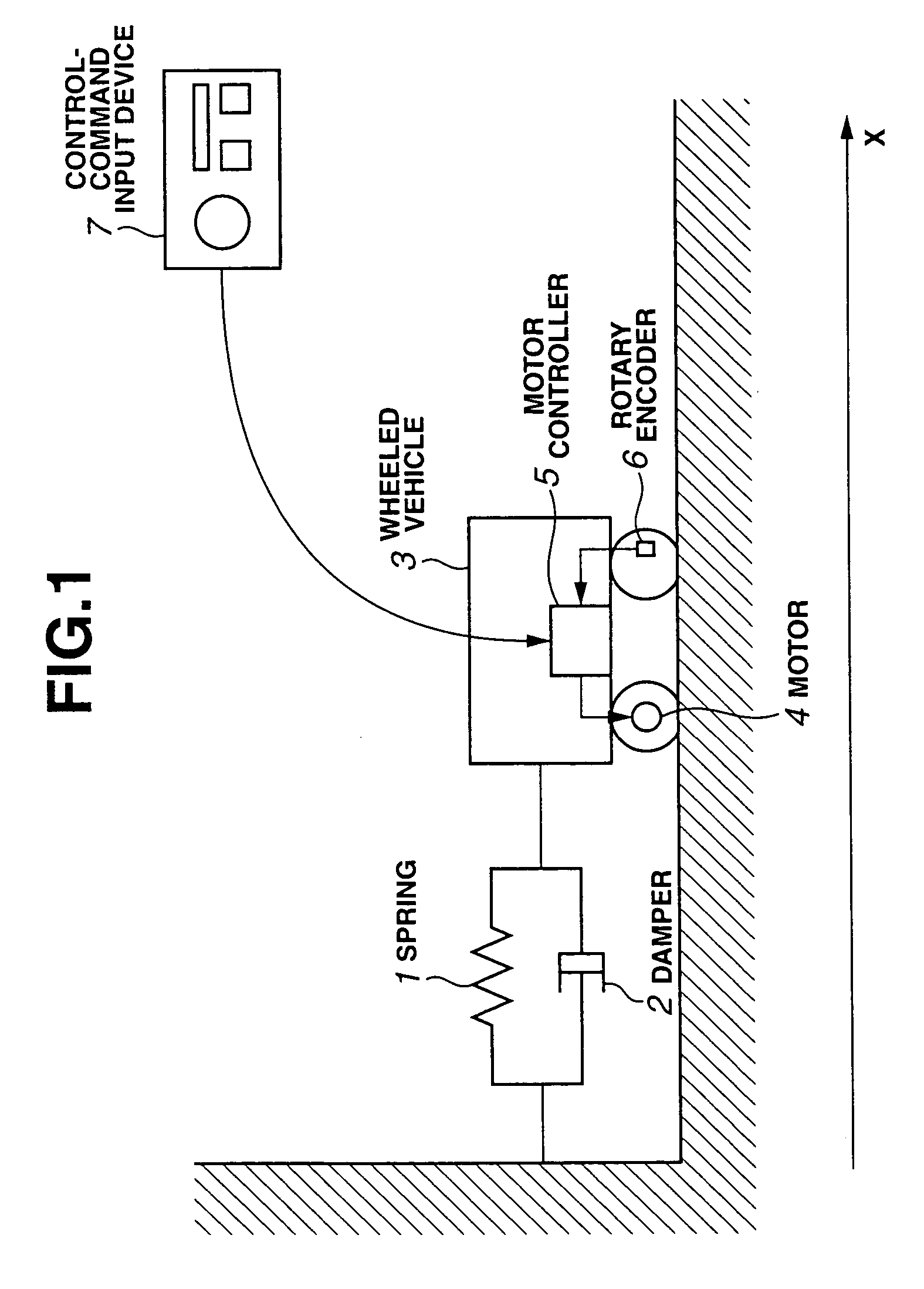
[0031]Referring now to FIGS. 1 through 4D, there is shown a model predictive control apparatus in accordance with the present invention. FIG. 1 is a schematic diagram of the model predictive control apparatus. As shown in FIG. 1, a wheeled vehicle 3 is connected to a left side wall through a spring 1 and a damper 2 disposed in parallel. Wheeled vehicle 3 is equipped with a motor 4, a motor controller 5 as a control unit, and a rotary encoder 6. Receiving a control command from a control-command input device 7, motor controller 5 actuates motor 4 to control a horizontal position of wheeled vehicle 3 in accordance with the control command. A coordinate system is defined so that its x-coordinate indicates the horizontal position of wheeled vehicle 3 and the origin point is a position of wheeled vehicle 3 in a condition in which spring 1 is in its neutral condition.

[0032]With u representing the torque generated by motor 4, the motion of wheeled vehicle 3 is described by the following di...

second embodiment

[0057]Referring now to FIGS. 5 through 11F, there is shown a model predictive control apparatus for an automotive vehicle in accordance with the present invention. FIG. 5 is a schematic diagram of the model predictive control apparatus. As shown in FIG. 5, the vehicle is equipped with an engine, cameras 8a, 8b, and 8c, a vehicle speed sensor 9, an electrical control unit (ECU) 10, a control-command input device 11, a throttle controller 12, a throttle actuator 13, brake controllers 14, and brake actuators 15. Front camera 8a includes a CCD camera, and mounted on the front portion of the vehicle to detect a plurality of target vehicles present in front of the vehicle, and to measure the positions of the target vehicles. In addition, front camera 8a is configured to monitor or recognize driving lanes of a road by detecting white marking lines on the road. Rear camera 8b is attached to the rear portion of the vehicle to detect a plurality of target vehicles present rearward of the vehi...


PUM


Abstract

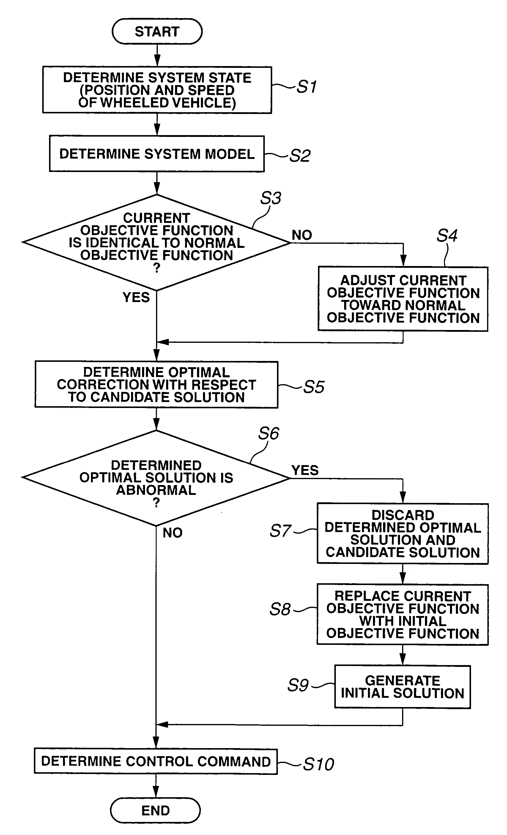
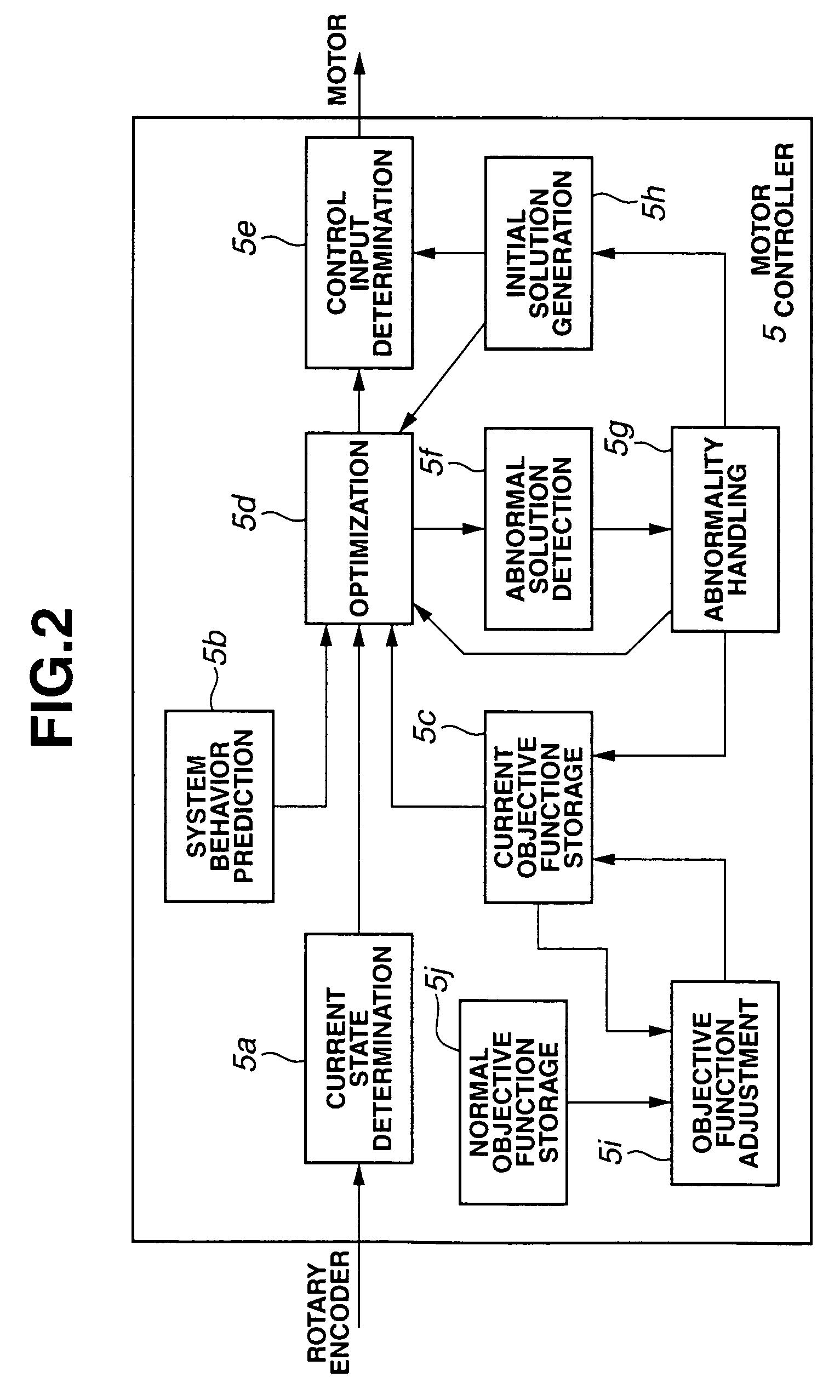
A model predictive control apparatus includes an initial solution generation section, an abnormality handling section, and an objective function adjustment section. The abnormality handling section performs initial solution generation when it is determined that performed optimization is abnormal. The initial solution generation section generates an initial optimal value of a future time series control input in accordance with an initial objective function, without reference to a candidate value of the time series control input. The objective function adjustment section adjusts the current objective function so that the current objective function varies stepwise with time toward the normal objective function when it is determined that the current objective function is different from the normal objective function.

Description

BACKGROUND OF THE INVENTION[0001]The present invention relates generally to model predictive control apparatus, and more particularly to model predictive control apparatus for automotive vehicles which predicts future dynamic behaviors of the host vehicle and target vehicles around the host vehicle, and optimizes a control input to the host vehicle in accordance with the prediction.[0002]In recent years, there have been proposed and disclosed various model predictive control (MPC, or model-based predictive control (MPDC)) systems. In general, a model predictive control method is configured to predict a time series of a state of a system in accordance with a mathematical model of the system, to define an objective function to numerically evaluate the predicted time series system state and a future time series of a control input to force the system state to track its setpoint, to calculate an optimal value of a future time series of the control input which minimizes the objective func...

Claims


Application Information

Patent Timeline
Patent Type & Authority Patents(United States)
IPC IPC(8): G06F17/10G05B13/04B60K31/00B60K31/04
CPCB60K31/0008B60K31/047Y02T10/84B60W50/0097B60W2050/0031
Inventor NISHIRA, HIKARUKAWABE, TAKETOSHI
Owner NISSAN MOTOR CO LTD
Learn More